13
3) Replacing DA-121D Valves
It is recommended that these valves be replaced at the same time as the diaphragms.
Use tools 1, 2, 5, and 6 listed above.
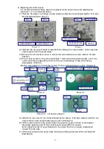
(1) Remove the stage 1 and stage 2 pump heads as described in 2) Replacing DA-121D and
DA-241S Diaphragms, step (1).
(2) Remove the hex socket head screws (M5×16) holding the valve retainer, and remove the
valve retainer from the pump head.
(3) Remove the old valves (A valve, C valve) and valve retainers( A valve retainer, B valve
retainer).
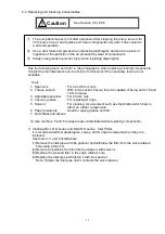
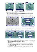
(4) Fit one new A valve to the pump head stage 1 inlet (mark facing downwards), one to the
outlet (mark facing upwards) and one to the pump head stage 2 inlet (mark facing
downwards). (Photo 8)
Attach a valve retainer on top of the A valve of the pump head stage 1 outlet. (Photo8-2)
(5) Attach one new valve C (no mark) followed by two pieces of B valve retainer and then a A
valve retainer to the pump head stage 2 outlet. (Photos 8-3)
(6) Fit the valve retainer to the pump head in the position shown in Photo 6, and tighten
diagonally opposite pairs of hex socket head screws (M5×16) equally.
Note: Check that the O ring is flattened to the extent that it is no longer visible when
viewed from the side.
(7) Fit the pump head to the pump while referring to 2) Replacing DA-121D and DA-241S
Diaphragms.
図3-7
Stage 1
M5
×
16
Valve retainer 1-1
e retain
r
1
Pump head
Photo 7
Inlet/exhaust pipe
Photo 6
Stage 2
Stage 1
Valve retainer 1-2
Valve retainer 1-1
Photo 8-2 121D series Stage 1
Photo 8
Stage 2
Stage 1
A valves
(one each)
Inlet
Inlet
Outlet
Outlet
A valve
(one)
Mark
A valve
retainer
A valve
retainer
①
C valve (no mark)
②
B v
alve retainer
(×2)
③
A
valve retainer
Photo 8-1
①
C valve (no mark)
③
A valve retainer
②
B v
alve retainer
B
A valve
Stage 1
Outlet
Stage 1
A valve
retainer
Outlet


