12
2) Replacing DA-121D series and DA-241S series Diaphragms
It is recommended that both diaphragms be replaced simultaneously.
Use tools 1, 2, 4, 5, 6 and 7 listed above. (Note: Always wear gloves.)
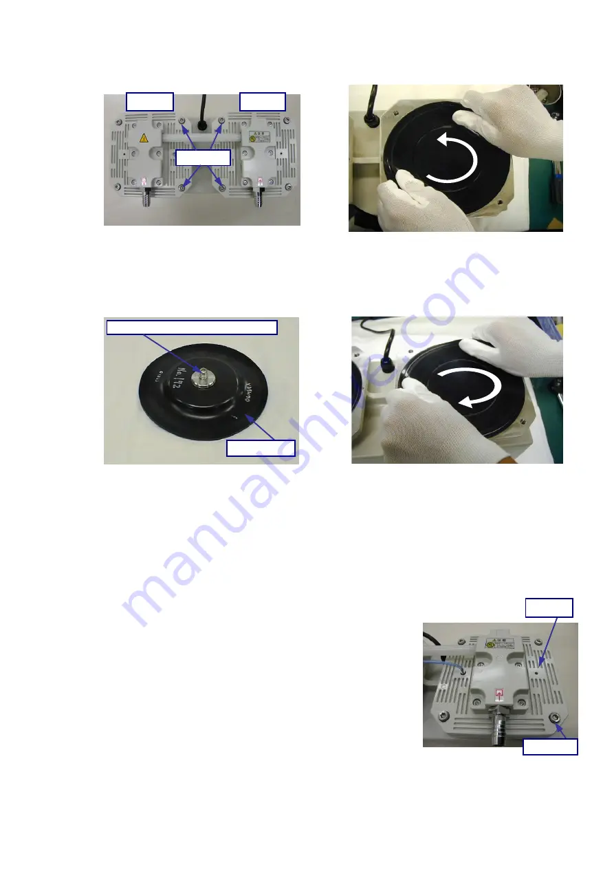
(1) Remove the eight M8×25 hex socket head screws shown in Photo 1.
(2) Lift the edge of the stage 1 diaphragm shown in Photo 2, turn it anti-clockwise, and
remove it.
Note: The diaphragm is more easily removed by two persons.
(3) Apply a small amount of vacuum grease to the hex socket head screw (M10×25, Photo 3)
at the rear of the new diaphragm to prevent scoring.
(4) Turn the diaphragm in the clockwise direction as shown in Photo 4 as far as it will go, and
tighten it a further 5
~
10°. Take care not to overtighten the diaphragm.
(5) Replace the stage 2 diaphragm as described in (2), (3) and (4).
(6) Using the torque wrench, tighten diagonally opposite pairs of the four stage 1 pump head
hex socket head screws (M8×25) equally to 18 N
・
m as shown in Photo 5.
(7) Fit the connecting pipe to the stage 1 side.
Note: Always fit the connecting piping from
the stage 1 side, and push it in as far
as possible.
(8) Using the torque wrench, tighten diagonally
opposite pairs of the four stage 2 pump head
hex socket head screws (M8×25) equally to
18 N
・
m.
(9) Close the inlet, set the switch to ON (ie to I),
and 2 hours later, use the torque wrench to
tighten diagonally opposite pairs of the eight
hex socket head screws (M8×25) equally to
20 N
・
m.
Photo 2
Photo 1
Stage 2
Stage 1
M8×25
Photo 4
Photo 3
Diaphragm
Hex socket head screw (M10×25)
1枚
Photo 5
M8×25
Stage 1

