background image

06 


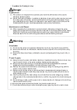
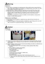
(4)  Do not hold or push the tube at the top of the pump (see below). Damage to the tube may 

affect performance of the pump. 


Operation


(5)  Touching rotating components (e.g. motor, main shaft, axial joints, cooling fan) while the 

pump is in operation may result in injury.


(6)  The overload protector operates when the pump becomes excessively hot. Touching it in this 

condition may result in burns. 

(7)  Touching the motor while the pump is in operation or while it is still hot immediately after 

having been switched off may result in burns. 

(8)  Do not insert fingers or objects into, or peer into, the inlet or outlet during operation. 


Maintenance and Repair 

(9)  If the pump ceases operation, turn power OFF (set switch to O) immediately to prevent 

accidents, remove the power cord from the wall outlet, and contact your dealer or the 
manufacturer for inspection and repair. 

(10) Leave the pump for at least 30 minutes until it has cooled, and begin operation again. 

Touching the pump immediately after it has stopped may result in burns. 


!

Caution


DA-241S series 

DA-121D series 

Summary of Contents for DA-121D Series

Page 1: ...t to Users Please read this manual thoroughly to ensure safe and effective use of the equipment Keep this manual in a safe place Due to periodic improvements in performance the equipment described in...

Page 2: ...09 Compressors and vacuum pumps Safety requirements Part2 Vacuum pumps IEC EN 61010 1 2010 A1 2019 Safety requirement for electrical equipment for measurement control and laboratory use Part1 General...

Page 3: ...related is in conformity with the following standards BS EN 1012 2 1996 A1 2009 Compressors and vacuum pumps Safety requirements Part2 Vacuum pumps BS IEC EN 61010 1 2010 A1 2019 Safety requirement fo...

Page 4: ...4 Cautions for Operation 4 1 Cautions for Operation 4 2 Operation of the Thermal Protector 4 3 Starting in Cold Weather 5 Pump Performance 5 1 Pressure Achieved 5 2 Evacuation Rate 5 3 Power Requireme...

Page 5: ...ies Dimensions Fig 3 1 Change region of the voltage and frequency Fig 3 2 Example of Piping Used When Evacuating a Vessel Table 1 1 Product Specifications 50 60 Hz Table 6 1 Consumables List Table 6 2...

Page 6: ...uipment correctly Read the section on Safe Use particularly closely Keep This Manual in a Safe Place After reading this manual be sure to keep it in a safe place which is readily accessible to others...

Page 7: ...outlet 2 3 Is the pump damaged in any way 4 Are any external screws or inlet and outlet pipes loose Are any components missing Contact your agent or the sales division of the manufacturer if there ar...

Page 8: ...esult in death or serious injury to the operator Incorrect handling of the equipment may result in death or serious injury to the operator Incorrect handling of the equipment may result in light or me...

Page 9: ...the pump 3 Ensure that the pump is freely ventilated to prevent overheating which may result in fire or burns Power Supply 4 Always remove the power cord before checking or repairing the pump Failure...

Page 10: ...ion of microscopic particles resulting from wear of components use a dust mask and gloves when replacing diaphragms valves and O rings Installation 1 To prevent back injuries always use at least two p...

Page 11: ...in operation or while it is still hot immediately after having been switched off may result in burns 8 Do not insert fingers or objects into or peer into the inlet or outlet during operation Maintenan...

Page 12: ...uiring appropriate caution during maintenance 5 Entry of corrosive gases organic solvents fluids or gases able to be condensed eg steam may result in damage to the pump and prevent normal operation 6...

Page 13: ...wer supply circuit automatically to prevent burn out if the motor temperature rises due to a pump fault which prevents rotation or if load becomes excessive Operating temperature 120 5 C 2 It is recom...

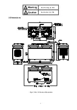
Page 14: ...See Warning 8 P04 See Caution 6 P06 2 Dimensions Warning Caution Fig 2 1 DA 121D series Dimensions...

Page 15: ...Fig 2 2 DA 241S series Dimensions...

Page 16: ...emperature when fitting the pump to equipment Use anti vibration rubbers to isolate the pump from vibrations in the equipment See 3 2 Environmental Conditions for Installation Storage and Operation fo...

Page 17: ...et to O and connect the power supply Note Ensure that the power cord is sufficient for the rated voltage and current Note Extension cords should be 3 wire with lead wires having a cross sectional area...

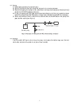
Page 18: ...t are not from our products please select the exhaust pipe that has same or larger inner diameter length with the inlet pipe 5 When evacuating a vessel ensure that a shut off valve is placed between t...

Page 19: ...fault has been removed wait until the motor cools and restart operation See Caution 6 P06 4 3 Starting in Cold Weather Cold weather will increase the viscosity of bearing grease and harden diaphragms...

Page 20: ...other gases resulting in increased pressure 5 2 Evacuation Rate The rate of evacuation for the pump varies with the type of gas entering the inlet and its pressure The maximum rate of evacuation is re...

Page 21: ...gs 6 2 Maintenance The following checks are required at least once every three days during operation 1 Check for abnormal noises 2 Check for abnormal heating of the pump 3 Check that gas is discharged...

Page 22: ...ced by the manufacturer s service division Replacement and Cleaning Guide Replace or clean components if performance is reduced or the following symptoms become apparent Inlet Filters Clean if dirty o...

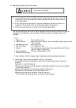
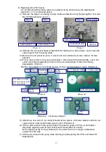
Page 23: ...A 121D series and DA 241S series Inlet Filters It is recommended that diaphragms valves and O rings be cleaned when they are replaced Use tools 3 5 and 6 listed above 1 Remove the inlet pipe with the...

Page 24: ...further 5 10 Take care not to overtighten the diaphragm 5 Replace the stage 2 diaphragm as described in 2 3 and 4 6 Using the torque wrench tighten diagonally opposite pairs of the four stage 1 pump h...

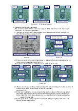
Page 25: ...ew valve C no mark followed by two pieces of B valve retainer and then a A valve retainer to the pump head stage 2 outlet Photos 8 3 6 Fit the valve retainer to the pump head in the position shown in...

Page 26: ...p head in the position shown in Photo 9 and tighten diagonally opposite pairs of hex socket head screws M5 16 equally See Photo 7 Note Check that the O ring is flattened to the extent that it is no lo...

Page 27: ...e retainer outlet side Replace it with a new outlet filter Install the outlet filter all the way in and check that it is not deformed after it has been installed Photos 11 1 11 2 6 Replacing the DA 24...

Page 28: ...d outlet pipes 7 Fit valve retainer 1 1 and 1 2 to the inlet and outlet pipes Note On the DA 241S fit valve retainer 2 1 Note Tighten the valve retainers until they are in contact with the inlet and o...

Page 29: ...other pump 2 Pressure measurement is incorrect 2 Measure the pressure correctly 5 1 3 Vacuum gauge is unsuitable 3 Measure with a calibrated vacuum gauge suitable for the pressure range 5 1 4 The inle...

Page 30: ...and inspection etc d Malfunctions caused by modifications or repairs carried out by a party other than the manufacturer or by a service company not approved by the manufacturer e Malfunctions caused...

Page 31: ...Industrial Safety and Health Law designates particular substances as the materials to be notified 2 Usage Status Operation Method Approx hours per day years and months Continuous Operation Intermitte...

Page 32: ...6 6397 2286 ULVAC KIKO Inc https ulvac kiko com en Please contact us for products Service Base or other Inquiries from here ULVAC Inc Components Division 2500 Hagisono Chigasaki Kanagawa 253 8543 Japa...

Reviews: