Issued/Revised:
48
DC-SAPLING w/ROOF
2
1
3
4
2
5
1
CM
0
INCH
0
10
9
6
11
14
8
15
7
12
13
4
3
6
5
02/02/16
800.458.5872
www.ultraplay.com
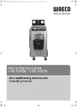
STEP 18
1. Place Upper Post Covers on to Upright Posts.
2. Attach 180 Degree Corner Connector to Slide Hood and Upper Post Cover 28.88" w/3 Inserts using M10 x 25mm B.H.C.S. Bolt. See
Detail 021.
Orientation of 180 Degree Corner Connector is critical. Refer to Detail A.
3. Attach 180 Degree Corner Connector to Slide Hood and Shapes Panel using M10 x 25mm B.H.C.S. Bolt. See Detail 021.
Orientation of
180 Degree Corner Connector is critical.
4. Attach Curved Leaf Connectors to Upper Post Covers and Slide Hood using M10 x 25mm B.H.C.S. Bolt. See Detail 021.
Orientation of
Curved Leaf Connectors is critical. Refer to Detail B.
5. Attach Upper Post Cover 21 1/2" w/2 Inserts and Uppper Post Cover 28 7/8" w/4 Inserts to Upper Post 60" using
M5 x 76mm Self-Tapping Screw. See Detail 085.
IMPORTANT: Position Upper Post Cover and drill Ø1/8" pilot hole.
Note: Orientation of Curved Leaf Connectors in relation to panels are critical.
6. Attach Curved Leaf Connector w/Recess to Upper Post Cover 21 1/2" w/2 Inserts and Upper Post Cover 28 7/8" w/4 Inserts using
M10 x 25mm B.H.C.S. Bolt. See Detail 021.
021
LEAF
CONNECTOR
M10 x 25mm (1")
BHCS BOLT
(33-11-0003)
PANEL
085
M5 x 76mm (3")
SELF-TAPPING
SCREW (33-11-0600)
INSERT
INSERT
DRILL Ø1/8"
PILOT HOLE
UPPER POST COVER
UPPER POST
Ø1/8" PILOT
HOLE
CENTERED
HORIZONTALLY
UPPER POST COVER
Summary of Contents for DC-SAPR
Page 1: ...Issued Revised 02 02 16 DC SAPLING w ROOF 800 458 5872 www ultraplay com 1 MODEL DC SAPR...
Page 2: ......
Page 8: ......
Page 9: ......
Page 10: ......
Page 15: ...Issued Revised 02 02 16 TOOLS REQUIRED 800 458 5872 www ultraplay com 14...