


g.
CAREFULLY
position the
FILTER TUB COVER
on the
OPEN
end of the Filter Tub with the
SLOT
on the cover seated around the Stand-
pipe/Docking Assembly. Then,
SECURE
the cover to the standpipe assembly by locking the latch on the cover.
h. Position the
ASSEMBLED
Filter Tub in front of the
FILTER TUB GUIDES
beneath the fryer; then
CAREFULLY
and
SLOWLY
insert the
Filter “Tub into the fryer until the
MALE
In Line Plug on the Docking Assembly seats in the
FEMALE
Bulkhead Coupling adjacent to the Drain
Valve Assembly.
4.
CLEANING THE FILTER TUB AFTER CLOSING
a. Repeat
DAILY
steps A 2 a through A 2 d page 18; then,
THOROUGHLY
clean the Filter Assembly as follows:
1)
THOROUGHLY
flush any remaining sediment from both sides of the filter
screen with
HOT WATER.
2) Grasp the
FINGER LOOP
on
FRAME A
and adjacent
FINGER LOOP
on
FRAME B
,
EVENLY
pull the frames apart; then
HINGE RAME A
to remove it from the
FILTER SCREENS
FIRST.
3) Grasp the
FINGER LOOP
on the straight side of
FRAME B
; then
HINGE
it to remove
FRAME B
from the
FILTER SCREENS
.
4) Separate the
UPPER
FILTER SCREEN
and
BAFFLE
from the
LOWER
FILTER
SCREEN.
5)
CAREFULLY
clean the two frames, screens and baffle in the 3 compartment
sink with hot water and allow these items to air dry.
DO NOT USE SOAP.
If necessary the channels in each frame can be cleaned with the edge of a scotch-
brite pad.
6) Insert the
SUCTION FITTING
on the BAFFLE in the hole of the
UPPER
FIL-
TER SCREEN; then place these items on top of the
LOWER
FILTER SCREEN.
7)
ENSURE
all sides of the FILTER SCREEN assembly are aligned, place the
PIN
end of
FRAME A
on the FILTER SCREENS, place the
CHANNEL
on the frame
adjacent to the
PIN
end over the FILTER SCREENS; then
HINGE
the frame so the
edge of the FILTER SCREENS are inserted in the other
CHANNEL
of FRAME A.
8) Place the
PIN
end of
FRAME B
on the FILTER SCREENS so the
PIN
is seated in
the
CHANNEL
of
FRAME A
near the
FINGER LOOP
, place the
CHANNEL
on
the frame adjacent to the
PIN
end over the edge of the FILTER SCREENS; then
HINGE
the frame so the edge of the FILTER SCREENS are inserted in the other
CHANNEL
of
FRAME B
and the
PIN
on
FRAME B
is seated in the
CHANNEL
of
FRAME A.
9) Adjust
FRAME A
and
B
so other
PINS
are properly seated in the
CHANNEL
of the opposite frame; then
CAREFULLY
connect
the
KNURL KNOB
and
STANDPIPE/DOCKING ASSEMBLY
to the
SUCTION FITTING
on the FILTER SCREEN assembly.
DO NOT OVERTIGHTEN!!!
B. WEEKLY
1. Perform the daily cleaning steps A 2 a through A 2 c on page 18.
.
2. Clean the Filter Assembly as follows:
a. Disassemble the filter and clean the two (2) frames as described in the Daily Steps on the previous page.
b. Place the upper and lower
FILTER SCREENS
in the fryer with
BOIL-OUT SOLUTION
for cleaning.
DO NOT PLACE THE
BAFFLE OR STANDPIPE/DOCKING ASSEMBLY IN THIS SOULUTION!!! BOIL-OUT
the fryer vat according to instruc-
tions contained in the cleaning manual provided by your chemical supplier.
c. After the filter screens have been cleaned in the Boil-Out Solution,
ENSURE
they are
THOROUGHLY
sprayed with a solution of
one (1)
PART
vinegar to
25 PARTS
of water to
NEUTRALIZE
the boil-out solution, then allow the screens to air dry.
NOTE:
Any residue of boil-out solution on the filter screens could cause the rapid break-down of the shortening.
d. Reassemble the “Micro-Mesh stainless steel filter screen as described in the
DAILY STEPS
on the previous page.
3. Place the
CRUMB CATCHER PAN
in the fryer with the Boil-Out Solution for cleaning, and after it is cleaned,
ENSURE
it is
sprayed with
a solution of vinegar/water as described in
WEEKLY
step B 2 c above.
4.
THOROUGHLY
clean the Filter Tub, and with
HOT SANITIZER SOLUTION
and allow them to air dry.
5. Re-assemble the Filter Tub as described in the
DAILY
steps on the previous page.
WARNING: WHEN ASSEMBLED, ENSURE THERE ARE NO FINGER LOOPS ON THE sTANDPIPE SIDE OF
THE MICRO-MESH FILTER.
OPERATION
A. GENERAL -
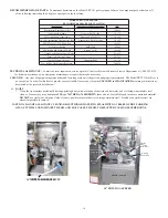
The “basic” Model ZRT3-H Gas Fryer is equipped with a Default-to-Manual-Restart (DTMR) Control, which uses an Electronic
Thermostat. Some fryers are equipped with an Ultrastat 11,21 or 25 Cooking Computer that use the same Temperature Sensing Prove. In this
section, the operation of the ZRT3-H Gas Fryer will cover the Default-to-Manual-Restart (DTMR) Control and the Ultrastat 11 Cooking Control.
B. DEFAULT-TO-MANUAL-RESTART (DTMR) CONTROL
18


