ULTRAFRYER ZRT3-H Operation Instruction Manual Download Page 15


3)  Turn the fryer ON/OFF switch to the 

ON

 position; then place the 

DTMR o

r other fryer control in the 

MELT MODE

.  


4)  When the 

BURNER TUBES

 are completely covered with 

LIQUID

 shortening and the shortening temperature has reached the appli-


cable 

MELT LIMIT TEMPERATURE,

 replace the grill in the fryer vat; then place the fryer in the 

FULL ON

 mode.


5)  Continue adding solid shortening as follows:


a)  Place small pieces of solid shortening into a fry basket.


b) 

CAREFULLY

 lower the basket into the fryer vat.


c) 

GENTLY

 turn the basket to allow these pieces of solid shortening to float away.


d)  Repeat the above steps until liquid shortening is even with the middle line of the 

“E     ”

 in the word LEVEL of the applicable 


shortening level mark on the rear wall of the fryer vat.

WARNING!!!           TO AVOID INJURY


DO NOT MOVE A FRYER FILLED WITH HOT LIQUID.


II  THE FRYER MUST BE RESTRAINED BY USE OF A RETAINING DEVICE TO PREVENT TIPPING TO AVOID THE 


SPLASHING OF HOT LIQUID.


III  THE AREA SURROUNDING THE FRYER MUST BE KEPT FREE AND CLEAR OF ALL COMBUSTIBLES.


IV  DO NOT GO NEAR THE AREA DIRECTLY OVER THE FLUE OUTLET WHEN THE FRYER’S MAIN BURNERS 


ARE OPERATING.


V  ALWAYS WEAR OIL-PROOF, INSULATED GLOVES WHEN WORKING WITH A FRYER FILLED WITH HOT OIL.


VI  ALWAYS DRAIN HOT OIL INTO A METAL TUB, POT OR CAN … HOT OIL CAN MELT PLASTIC BUCKETS OR  


SHATTER GLASS.

START-UP AND COOKING 
 

A.  GENERAL :  


1.  The Default-to-Manual-Restart (DTMR) Control along with a Fenwal


Temperature Controller or Electronic Thermostat is connected to a fryer’s 


electrical system to control operation of the fryer.   The DTMR contains a 


Default-to-Off circuit that will 

DISABLE

 the fryer anytime the Drain Valve


is 

OPEN

, and a Default-to-Melt circuit that will automatically place the fryer 


in a 

SHORTENING MELT MODE 

to gradually and safely heat shortening 


each time the fryer’s Toggle ON/OFF Switch is turned 

ON.


2.  Electronic Thermostat:  

The Electronic Thermostat has a temperature 


range from 200ºF (93ºC) to 400ºF (204ºC) and will accurately maintain a 


pre-set shortening cook temperature within ± 2º of the pre-set temperature.


B.  START-UP :  


1. 

TO TEST OPERATE 

an Ultrafryer Gas Fryer equipped with a Default-to-Manual-Restart (DTMR) control:

                        a.     Ensure the fryer’s Toggle ON/OFF Switch is in the 

OFF 

position.

                        b.     Fill the fryer vat with hot or cold water to the middle of the 

“E←” 

in the word 

LEVEL

 of the applicable shortening level mark 

                                on the rear of the vat.
                        c.     Turn the MANUAL gas valve to the 

OFF

 position and wait 

FIVE


(5)

 minutes for any accumulated gas to disperse.

                        d.     

ENSURE

 the 

MAIN

 gas shut-off valve is in the 

ON 

position, and that the 

EXHAUST FAN

 is 

ON

.

                        e.   Turn the MANUAL GAS VALVE to the ON position.


f.   Perform the following steps, in the order listed:

11

ITEM

ACTION

DTMR CONDITION

1

ENSURE

 the drain valve handle is in the CLOSED

UP

 position and that water is at the proper level; then 

turn the Toggle ON/OFF switch to the 

ON

 position.

A.  

BLUE READY 

 TO START lamp will 

LIGHT.


CAUTION:  PRIOR TO PROCEEDING TO STEP 2 VISUALLY CHECK THAT THE HEAT MECHANISM IS

    COVERED WITH AT LEAST 2”  (51 mm) OF WATER.

2

Depress, then release the momentary 

START

 button

A.  

RED STARTED

 lamp and 

AMBER MELT 

      MODE 

  lamp will light.

B.  

BLUE READY TO START

 lamp will turn 

OFF.

C.  A 

TIMER

 in the Default-To-Melt electrical circuit 

     will begin cycling the fryer heat mechanism 

ON 

for  

     seven (7) seconds and 

OFF

 for 28 seconds  to safe-     

     ly heat the water.     


CAUTION:  PRIOR TO PROCEEDING TO STEP 3, VISUALLY CHECK THAT THE WATER 

     COMPLETELY  COVERS THE HEAT MECHANISM.

3

When the shortening temperature is above 100ºF 

(38ºC) depress, then release the momentary 

EXIT 

MELT 

button.

A.  

AMBER MELT MODE 

lamp will turn 

OFF 

and


the 

RED STARTED 

lamp will remain lit.

B.  The 

TIMER

 in the Default-To-Melt circuit will 

      switch to the 

FULL ON 

position, allowing the 

      Fenwall thermostat or Electronic Thermostat to 

      heat water to its pre-set temperature.

4

When the fryer’s 

RED

 heat indicator lamp turns 

OFF

, indicating the pre-set temperature has been 

reached, initiate a cook cycle.


 Steps 1, 2 and 3 will have to be repeated each time any of the following occurs:


DRAIN VALVE IS OPENED.

                  TOGGLE  ON/OFF SWITHCH IS TURNED OFF TO FILTER SHORTENING.

                  TOGGLE  ON/OFF SWITCH IS TURNED OFF AT CLOSING.

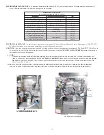
ELECTRONIC THERMOSTAT

��� ������� ����

����� ����

���� ����

���� �����

�� �����

����

�����
������

���� ����

������

Summary of Contents for ZRT3-H

Page 1: ...r Lane P O Box 5369 San Antonio Texas 78201 800 525 8130 210 731 5000 Fax 210 731 5099 WARNING TO PRECLUDE THE POSSIBILITY OF SPONTANEOUS COMBUSTIBLE FILTER TUB FIRES SLUDGE AND CRUMBS MUST BE REMOVED...

Page 2: ...nt Ultrafryer Systems for use by personnel who will operate a 14 or 18 Model ZRT3 H Gas Fryer equipped with an EZ Dock Filtration System TECHNICAL PUBLICATIONS DEPARTMENT ULTRAFRYER SYSTEMS 302 SPENCE...

Page 3: ...on Electrical Connections Default To Manual Restart DTMR Control Optional Controls INITIAL START UP Cleaning Start up Lighting Instructions Sequence Of Ignition Burner Operation Test Shortening Instal...

Page 4: ...1 Cooking Computer Filtering Shortening Filter Tub Assembly Installation Filtering Polishing Shortening Fryer Boil Out Shortening Disposal Shortening Installation TECHNICAL ASSISTANCE ORDERING INFORMA...

Page 5: ...GENERAL INFORMATION 1...

Page 6: ...fy an authorized service agent to make repairs during normal hours or after hours Any parts that need to be shipped back to Ultrafryer Systems will be shipped back prepaid by the customer marked with...

Page 7: ...rs may request the fryer be equipped with an Ultrastat 21 or Ultrastat 25 Cooking Computer In addition the 14 18 Model ZRT3 H are equipped with the NEWLY developed EZ Dock Filtration System that uses...

Page 8: ...14 MODEL ZRT3 H GAS FRYER 18 MODEL ZRT3 H GAS FRYER 14 18 MODEL ZRT3 H GAS FRYER CONTROL LOCATIONS 4...

Page 9: ...previous page AUTOMATIC SAFETY FEATURES A High limit thermostat to shut off gas to the main burners by opening a solenoid actuated safety valve in the combination gas control valve B Combination gas...

Page 10: ...ryer and main gas regulator locate the FT3 HR M3 HR of gas required for the fryer and pipe length and read the pipe diameter on the top row For example a 14 ZRT3 H fryer operating on NATURAL GAS requi...

Page 11: ...when installed must conform to the current NFPA 54 1 and Canadian CAN CGA 1 11 latest edition NOTE Local building codes will usually not permit a fryer with its open tank of hot oil to be installed i...

Page 12: ...R S COMBINATION GAS CONTROL VALVE EXCEEDS 1 2 lb in2 035 kg cm2 OR APPROXIMATELY 14 356 mm W C AN EXTERNAL REGULATOR MAY BE NEEDED TO PREVENT DAMAGE TO THE COMBINATION GAS VALVE AND VOIDING OF WARRANT...

Page 13: ...START BUTTON When this button is momentarily depressed it places the fryer in operation RED STARTED LAMP When lit indicated the START BUTTON has been momentarily depressed and the fryer is operating A...

Page 14: ...valve behind the fryer control access door of the fryer to the OFF position and wait FIVE 5 minutes for any accumulated gas to disperse 4 ENSURE the MAIN gas shut off is in the ON position MANUAL VAL...

Page 15: ...pre set shortening cook temperature within 2 of the pre set temperature B START UP 1 TO TEST OPERATE an Ultrafryer Gas Fryer equipped with a Default to Manual Restart DTMR control a Ensure the fryer...

Page 16: ...IT MELT key HEAt will appear in the computer display to indicate it is in the FULL ON mode 3 Depress the TEMP key ONCE The ACTUAL water temperature will be shown in the computer display NOTE DEPRESS T...

Page 17: ...If shortening is needed use the filter scraper to cut off a small block of solid shortening 3 Place the small block of shortening into a fry basket lower the basket into the shortening then turn the...

Page 18: ...ng handle skimmer to pull congealed shortening UPWARD from the Cold Zone area 6 When shortening has reached the set temperature and the RED indicator lamp on the fryer has turned OFF allow the Electro...

Page 19: ...y have over heated and shut off on thermal over load If this situation did occur it will correct itself when the mo tor cools 10 20 minutes If this overheating problem persists re place the blower mot...

Page 20: ...rtment at 1 800 525 8130 for technical assistance or to perform any maintenance or repair that may be necessary CLEANING Any item of equipment operates better and lasts longer when it is kept clean an...

Page 21: ...t FINGER LOOP on FRAME B EVENLY pull the frames apart then HINGE FRAME A to remove it from the FILTER SCREENS FIRST c Grasp the FINGER LOOP on the straight side of FRAME B then HINGE it to remove FRAM...

Page 22: ...re inserted in the other CHANNEL of FRAME B and the PIN on FRAME B is seated in the CHANNEL of FRAME A 9 Adjust FRAME A and B so other PINS are properly seated in the CHANNEL of the opposite frame the...

Page 23: ...the OFF position and wait FIVE 5 minutes for any accumulated gas to disperse 3 ENSURE the MAIN gas shut off valve is in the ON posi tion and that the EXHAUST FAN is ON 4 Turn the MANUAL gas valve to t...

Page 24: ...display ACTUAL TEMPERATURE when depressed ONCE Used to display SETPOINT TEMPERATURE when depressed TWICE Used to display remaining TIME when depressed THREE TIMES EXIT MELT 1 Used to manually exit the...

Page 25: ...MP key THREE 3 times 4 Steps 1 2 3 and 4 will have to be repeated each time any of the following occurs DRAIN VALVE IS OPENED FRYER TOGGLE ON OFF SWITCH IS TURNED OFF TO FILTER SHORTENING OR BOILOUT A...

Page 26: ...le sediment and debris on the heat exchanger and vat sides push in the Vat Shortening RETURN LEVER and procede to the following paragraph g below g An AUTOMATIC VAT CLEANER AVC Spray Blaster is an opt...

Page 27: ...ENING INSTALLATION A GENERAL Shortening in the Model ZRT3 H Gas Fryer should be BOILED OUT every 7 DAYS to remove carbon buildup and other encrusted material B SHORTENING DISPOSAL 1 CAREFULLY assemble...

Page 28: ...ilter tub C BOIL OUT Boil out the ZRT3 H Gas Fryer following the cleaning instructions in the Cleaning Manual provided by your approved chemical supplier The following are generic proceduress DTMR EQU...

Page 29: ...E HANDLE to the closed UP position then fill the fryer with NEW shortening to the applicable shortening level mark as prescribed below 13 Reprogram the Ultrastat 11 Cooking Computer for the correct co...

Page 30: ...nd will gladly assist you in preparing and processing of the necessary claims only if proper notification has been accomplished on the carrier delivery document Damaged equipment and or containers mus...

Page 31: ...THIS PAGE INTENTIONALLY LEFT BLANK...

Page 32: ...27 ULTRAFRYER MOCEL ZRT3 H GAS FRYER FRONT VIEW 14 ZRT3 H 18 ZRT3 H...

Page 33: ...Drain Ball Valve Assembly 19A564 17 Ignitor Spark Rod Assembly w Ignitor Rod Set Rod Gap to VVE 4mm prior to installation 19A738 18 Sound Weldment Baffle 19A739 19 Docking Release Handle 19A948 20 14...

Page 34: ...8 High 146 x 208mm Rectangular Flue Tube with deflector 18 Model ZRT3 H 73 4 x 111z High 197 x 281mm Rectangular Flue Tube with deflector 19A910 19b312 7 125 Volt 75 Watt Silicon Heater 5 1524mm Long...

Page 35: ...R Lens 23A056 6 COOKING CONTROLS Default To Manual Restart DTMR Control f 14 18 Model ZRT3 H Uses Electronic Thermostat PN 12B077 Ultrastat 11 Cooking Computer Uses Temperature Probe 18A006 12B014 22A...

Page 36: ...edium Duty Caster 28A005 ITEM DESCRIPTION PN 1 6 1829mm Wash Down Hose w Fittings 12 54 2 Wash Down Hose Nozzle Assembly 12 675 3 Proximity Sensor Switch 18A060 4 Cool II Handle 22 734 5 1 2 13mm S S...

Page 37: ...I Handle 22 734 3 1 2 13mm HH 2236 SQ Spray Nozzle 22A111 4 1 2 13mm x 90 Black Iron Elbow 24 007 5 1 2 13mm 5 Way Black Iron Crossover Manifold 24A082 6 14 ZRT3 H 1 2 13mm x 51 4 133mm Black Iron Nip...

Page 38: ...33 15 0 WIRING DIAGRAM Since minor wiring changes may occur in the future USE the diagram pasted to the fryer for circuit tracing and or troubleshooting a Model ZRT3 H Gas Fryer...

Reviews: