


17
2. The Filter Tub Assembly and Filter Screen should be cleaned
EACH DAY
after
FILTERING
and
AT CLOSING
and
THOROUGHLY
cleaned once
each week. To remove the Filter Tub Assembly from the fryer:
a.
OPEN
the Fryer’s Temperature Control Access Door,
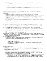
b.
DEPRESS
the
DOCKING RELEASE HANDLE
, shown to the right.
c.
PULL
the Filter Tub Assembly from the fryer.
d.
Disassemble the Filter Tub Assembly in the following sequence:
1). filter tub cover
2) crumb catcher screen
3) filter screen standpipe/docking assembly; then separate the
standpipe/docking assembly from the filter screen
e. Clean the Filter Tub and Filter Screen as follows:
�����������������
��������
������ ���
�����
������ ���
�����
����� ������� ������
FILTER TUB
OUT OF FRYER
��������� � �������
������ ���
�����
�����
������� ������
��������
������ ������
��������
������ ���
����
�������
����
�������
������
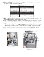
3.
CLEANING THE FILTER TUB AFTER FILTERING SHORTENING
a. Disassemble the Filter Machine by removing the following items in the order listed; 1)
FILTER TUB COVER,
2)
CRUMB CATCHER
SCREEN
,
3) FILTER SCREEN W/STANDPIPE/DOCKING
attached
;
then 4) separate the
STANDPIPE
and
DOCKING
ASSEMBLY
from the Filter Screen.
b. Clean the Wash Down Hose with santizer solution; then hang the Wash Down Hose in an upright position so shortening can drain into a
container.
c. Discard crumb fragments in the Crumb Catcher Pan and
THOROUGHLY
clean the pan with
HOT
water and let it air dry.
d. Raise the Filter Assembly with Standpipe and Docking Assembly attached, above the Filter Tub and let any sediment or shortening drain
into the tub; then separate the standpipe/docking assembly from the Filter Screen and clean the assembly with santizer solution and wipe it
dry with a lint free cloth.
THOROUGHLY
clean the filter assembly as follows:
1) “Micro-Mesh” Stainless Steel Filter Screen
(a)
CAREFULLY
remove any debris from the screen using a scraper.
(b) Grasp the
FINGER LOOP
on
FRAME A
and adjacent
FINGER LOOP
on
FRAME B
,
EVENLY
pull the frames apart; then
HINGE
FRAME A to remove it from the
FILTER SCREENS
FIRST.
(c) Grasp the
FINGER LOOP
on the straight side of
FRAME B
; then
HINGE
it to remove FRAME B from the
FILTER
SREENS.
(d) Separate the
UPPER
FILTER SCREEN
and
BAFFLE
from the
LOWER
FILTER SCREEN
.
(e)
CAREFULLY
clean the two frames, screens and baffle in the 3 compartment sink with hot water and allow these items to air
dry.
DO NOT USE SOAP.
If necessary the channels in each frame can be cleaned with the edge of a scotch-brite pad.
(f) Insert the
SUCTION FITTING
on the
BAFFLE
in the hole of the
UPPER
FILTER SCREEN
; then place these items on top of
the
LOWER FILTER SCREEN
.
(g)
ENSURE
all sides of the
FILTER SCREEN
assembly are aligned, place the
PIN
end of
FRAME A
on the
FILTER
SCREENS
, place the
CHANNEL
on the frame adjacent to the
PIN
end over the FILTER SCREENS; then
HINGE
the
frame so the edge of the FILTER SCREENS are inserted in the other
CHANNEL
of FRAME A.
(
h) Place the
PIN
end of FRAME B on the FILTER SCREENS so the
PIN
is seated in the
CHANNEL
of FRAME A near the
FINGER LOOP
, place the
CHANNEL
on the frame adjacent to the PIN end over the edge of the FILTER SCREENS; then
HINGE
the frame so the edge of the FILTER SCREENS are inserted in the other
CHANNEL
of FRAME B and the
PIN
of
FRAME A is seated in the
CHANNEL
of FRAME B.
(i) Adjust
FRAME A
and
B
so both
PINS
are properly seated in the
CHANNEL
of the opposite frame; then
CAREFULLY
connect the
KNURL KNOB
on the
STANDPIPE/DOCKING ASSEMBLY
to the
SUCTION FITTING
on the FILTER
SCREEN assembly.
DO NOT OVERTIGHTEN!!!
e. Remove any sediment and shortening in the Filter Tub using a scraper; then wipe the tub dry with paper towels.
f.
CAREFULLY
insert the assembled Filter Screen in the bottom of the Filter Tub; then
CAREFULLY
insert the Crumb Catcher Pan in
the Filter Tub with the
DRAIN VALVE
Docking Flange over the leading edge of the pan.


