ULTRAFRYER F-E21-14 Operation Instructions Manual Download Page 26


PN 30A255 June 2014 Rev A 

26 

FRYER BOIL-OUT 
 
BOIL-OUT 

each fryer following cleaning instructions contained in the Cleaning Manual provided by your approved chemical 

supplier. The following are generic procedures: 
 
1) Ensure Drain Lever is in the closed position, then add water to vat until it reaches a point 2" (51 mm) BELOW the middle of 
the UPPER shortening level mark on the rear wall of the vats. 
 

WARNING 
ONLY USE A COMMERCIAL GRADE “NON CHLORINE” BOIL-OUT COMPOUND !! 
 

2) Add the amount of 

BOIL-OUT COMPOUND 

in the fryer vat as prescribed in the Cleaning Manual 

provided by the Chemical Supplier. 
 
3)Turn the Power ON/OFF switch for the fryer to the 

ON

 position; then depress the Computer ON/OFF Button to the 

ON

 position. 

 
4) Place the computer in the 

BOIL MODE 

by pressing the TEMPERATURE Button and the number 2, 1, 2 Buttons 


NOTE 

BOIL 30:00 will appear in the computer display 
The HEAT DEMAND LED on the computer and the RED Heating Indicator Lamp on the fryer will cycle ON and OFF to heat 
the water to 192 Deg F (89 Deg C) 


5) Frequently scrub the sides, front and rear of the fryer vat with a long handled synthetic bristle scrub brush. 
 
6) After the boil-out solution has 

BOILED

 for 30 minutes and the alarm sounds, press the ON/OFF key to 

EXIT BOIL 

MODE

 
7) 

Turn the Power ON/OFF Switch for the fryer to the OFF position and CAREFULLY dispose of the boil-out solution in a 

floor drain. 


8) Use a scrubbing pad to remove carbon buildup from the Electric Elements until all encrusted material has been removed. 
 
9) Rinse the vat with hot water until the water coming out of the drain valve is clear. 
 
10) Mix a solution of ONE PART vinegar to 25 PARTS of water. Place this mixture into a one gallon garden pressure sprayer; 
and THOROUGHLY spray this solution onto the SIDES, ELECTRIC ELEMENTS, and BOTTOM of each vat to neutralize the 
Boil-Out Compound.


NOTE 

Boil-Out Compound will cause shortening to break down rapidly if it is not neutralized. 


11) 

THOROUGHLY

 wipe the sides, electric element, and bottom of the vat with clean, lint-free, dry towels to 

remove any remaining water; then fill each fryer with 

NEW

 shortening following shortening installation procedures in this 

manual. 
 
12) After the fryer has been filled with new shortening, place the computer in the 

FEATURE PROGRAMMING MODE 

and set the 

DISPOSAL 

HIT 

COUNT ( DHC 

#####) 

to "0" to clear the 

DISPOSE PROMPT

then press the 

SET


key on 

the computer to exit the programming mode and return to normal operation.


SHUT DOWN PROCEDURES 

 
1. Ensure the Computer’s ON/OFF Button is in the OFF position 
2. Ensure the Fryer’s Power ON/OFF Switch is in the OFF position 

CAUTION:  
TURN OFF FRYER POWER BEFORE LIFTING HEATING ELEMENTS OUT OF WATER 
OR SHORTENING 

Summary of Contents for F-E21-14

Page 1: ...or main tenance can cause property damage injury or death Read the installation operating and maintenance instructions thor oughly before installing or servicing this equipment PN 30A255 June 2014 Re...

Page 2: ...s are identified as follows NOTE CAUTION To assure producing a quality product while prolonging the life expectancy of the fryer ensure that the boil out and cleaning instructions are strictly followe...

Page 3: ...ANCE AND TROUBLESHOOTING Preventive Maintenance 18 Troubleshooting 19 Troubleshooting Chart 19 Cleaning General 21 Daily 21 Weekly 21 FRYER OPERATION General 23 24 Ultrastat 25 Cooking Computer 25 Sho...

Page 4: ...GENERAL INFORMATION PN 30A255 June 2014 Rev A 4...

Page 5: ...PN 30A255 June 2014 Rev A 5...

Page 6: ...ld never be operated with wet hands or while standing in water To do so can result in serious electrical shock or death Fire in liquid shortening should always be a constant concern of team members op...

Page 7: ...at 25 Cooking Computer and the Red Heating Indicator Lamp these controls are mounted on the Controller Door The Temperature P robe and Hi Limit Switch these controls are located inside the vat The Dra...

Page 8: ...ns MODEL 14 356 mm ED14 ELECTRIC FRYER 8 PN 30A255 June 2014 Rev A Temperature Probe Hi Limit Switch Ultrastat 25 Cooking Computer Power On Off Switch Red Hi Limit Indicator Lamp Electrical Box Assy R...

Page 9: ...TURES 1 Hi Limit Thermostat Switch with Auto Reset 2 Red Hi Limit Indicator Lamp to indicate hi limit has been exceeded 3 Ultrastat 25 Controller will power off when hi limit has been exceeded 9 PN 30...

Page 10: ...PRE INSTALLATION PN 30A255 June 2014 Rev A 10...

Page 11: ...0 latest edition In Canada electrical installation must be in accordance with the current Canadian Electrical Code CSA C22 1 and CSA 22 1 as applicable and or local codes 2 Other applicable nationally...

Page 12: ...RECEIVING AND INSTALLING PN 30A255 June 2014 Rev A 12...

Page 13: ...cation and that provisions are made so that the fryer can be moved to service fryer from the rear Electrical connec tions to the fryer should be made by a licensed electrician and they must conform to...

Page 14: ...tal LED readout and display board the Ultrastat 25 Cooking Computer has been customized for Ultrafryer Systems applications by the addition of up to 1O stage cooking profiles for each of the 8 product...

Page 15: ...INITIAL START UP PN 30A255 June 2014 Rev A 15...

Page 16: ...ure the Fryer s Power ON OFF Switch is in the ON position 2 Ensure the Computer s ON OFF Button is in the OFF position 3 Ensure the Drain Ball Valve Lever is CLOSED 4 Fill the fryer vat with hot or co...

Page 17: ...PREVENTIVE MAINTENANCE AND TROUBLESHOOTING PN 30A255 June 2014 Rev A 17...

Page 18: ...r is required all electrical power MUST BE TURNED OFF PRIOR TO performing that service or repair PREVENTIVE MAINTENANCE SCHEDULE DAILY ITEM INSPECT FOR Grease Filters Clean grease filters in the exhau...

Page 19: ...n AUTHORIZED repairman and or Ultrafryer Systems Customer Service 1 800 525 8130 and provide the infor mation acquired while performing these checks CAUTION ENSURE REPAIRMEN ARE ADVISED THAT FRYER RES...

Page 20: ...CLEANING PN 30A255 June 2014 Rev A 20...

Page 21: ...material DO NOT use steel wool abrasive cloths cleaners powders metal knife spatula or any other metal object to scrape stainless steel Scratches on stainless steel are almost impossible to remove 2...

Page 22: ...PN 30A255 June 2014 Rev A 22 FRYER OPERATION...

Page 23: ...MELT MODE each time it is turned ON and controls the COOK CYCLES of each product 23 PN 30A255 June 2014 Rev A Controller Door Service Access Door Temperature Probe Hi Limit Switch Ultrastat 25 Cookin...

Page 24: ...ical Box Assembly 24 PN 30A255 June 2014 Rev A Mercury Contactor Relay 24 VAC Transformer Terminal Block Relay 24 VDC Mechanical Contactor Fuse Holder And Fuses Wires removed from Electrical Box for c...

Page 25: ...T UP To operate an Ultrafryer Electric Fryer equipped with an Ultrastat 25 Cooking Computer 1 Ensure the Fryer s Power ON OFF Switch is in the ON position 2 Ensure the Computer s ON OFF Button is in t...

Page 26: ...T BOIL MODE 7 Turn the Power ON OFF Switch for the fryer to the OFF position and CAREFULLY dispose of the boil out solution in a floor drain 8 Use a scrubbing pad to remove carbon buildup from the Ele...

Page 27: ...PN 30A255 June2014 Rev A 27 TECHNICAL ASSISTANCE ORDERING INFORMATION...

Page 28: ...pected for damage to shipping containers prior to departure of the delivering carrier Any damage must be notated on the receiving document to facilitate filing of freight claims Carriers must be notif...

Page 29: ...PN 30A255 June 2014 Rev A 29 RECOMMENDED SPARE PARTS...

Page 30: ...f the following items should be kept as a spare part in the local area 30 PN 30A255 June 2014 Rev A Description P N U25 Controller 22A621 Hi Limit Switch 18A364 Mechanical Contactor 18A103 Mercury Con...

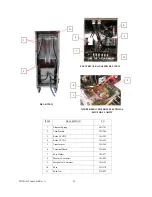
Page 31: ...PN 30A255 June 2014 Rev A 31 PARTS IDENTIFICATION...

Page 32: ...e description and part number Use that part number when ordering a replacement part ITEM DESCRIPTION PN 1 U25 Controller 22A621 2 Snap Light Red 23A103 3 Drain Ball Valve 24A204 4 Toggle Switch 18 204...

Page 33: ...24 VDC 18A301 4 Relay 24 VAC 18A034 5 Transformer 18A368 6 Terminal Block 23A428 7 Fuse Holder 23A277 8 Mercury Contactor 18A026 9 Mechanical Contactor 18A103 10 Fuse 23A278 11 Push Nut 27A087 10 2 8...

Page 34: ...PN 30A255 June 2014 Rev A 34 WIRING DIAGRAM...

Page 35: ...PN 30A255 June 2014 Rev A 35...

Page 36: ...PN 30A255 June 2014 Rev A 36 ACCEPTABLE ALTERNATE AND REQUIRED HI LIMIT CONSTRUCTION...

Page 37: ...e U S Fryer on the previous pages with the exception of a Hi Limit The 18A371 Hi Limit described below is the ONLY Hi Limit to be used to meet the requirements for a Canada Fryer Locate the part below...

Reviews: