Installation, Maintenance and Owner's Manual
ULTRAFLEX
page 36
of 143-
POWER ASSISTED STEERING SYSTEM
E
N
G
L
ISH
3.7.3 User interface cable
3.7.2Key cable
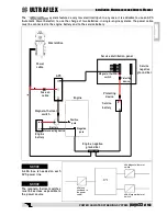
Two engine keys can be connected to the cable.
The black wire and the red wire are used in the same way; therefore, a wiring diagram is not necessary.
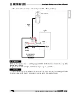
In single-engine systems, it is sufficient to connect one key wire to the positive wire of the panel key.
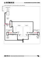
In twin-engine systems, it is necessary to connect both key wires to the positive wires of the panel keys.
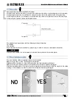
In three-engine systems, follow the diagram below:
The installer must use diodes with the following minimum features:
Id = 200mA
Vbr = 32 VDC
Key connectors must be connected in a proper way, in order to ensure a waterproof connection
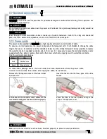
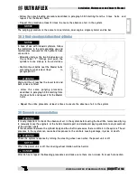
The user interface cable is supplied ready to be connected.
Make sure you hear a "click" confirming the connection.
Slightly pull the connector to check that connection has been properly performed.
Make sure the user interface cable is not stretched: the connector could be damaged.
Possible exceeding parts of the cable must be properly wound and fixed so that the weight of the cable
winding is not excessive in order to prevent the connector from being damaged.
NO
YES
2
nd
engine key
3
rd
engine key
Wire of the key cable
NOTICE
In case of dual station, it is not necessary to connect the key cable to the second panel.

