
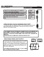
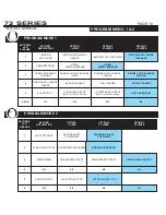

Press Lock
Press Unlock
Press Start
Press #
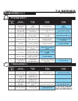
MENU 1
MENU 2
MENU 3
MENU 4
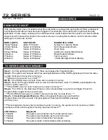
1 - Cycle the Ignition Key On/Off On/Off On (Leaving the key ON)
2 - Press and release the Program Switch located on the antenna 1 time.
*The Horn will chirp and the park light will turn on to confirm that the system
has entered Program Mode.
3 - Select the Program Menu by pressing the button that corresponds to the
desired Program Menu.
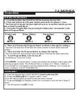
ENTERING PROGRAM MODE
1 -
Cycle the Ignition Key On/Off On/Off On (
Leaving the key ON
)
2 -
Press and
RELEASE
the Program Switch 1 time.
(Horn will chip to confirm program mode has been entered)
3 -
Press and
HOLD
the Program Switch for 5 seconds or until the Horn Chirps 3
times.
4 - Turn the ignition key
OFF
to exit.
4 - Press and Release the Program Switch to advance through the settings.
*The horn will chirp and LEDs flash the same number of times as the selected
setting.
5 - Press and hold the Program Switch to change the setting
.
(The horn will honk and the park lights will flash to indicate the option selected)
6 -
To exit Program Mode, turn the key off.
(Confirmed by Long Horn Chirp)
1172 SERIES-
To access Menu 1 press and release the program switch again after
entering program mode. The LEDs will flash in a series of 1. (Menu 1 Setting 1)
To access Menu 4 the system must be programmed for Setting 1 or 2 in program
menu 3 setting 9. (2 BUTTON REMOTE)
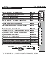
SYSTEM RESET
SYSTEM PROGRAMMING -
Menu 1
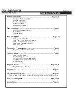
PAGE 8
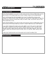
INSTALL MANUAL
TRANSMITTER PROGRAMMING
72 SERIES
SYSTEM PROGRAMMING -
Menu 1
PAGE 9
INSTALL MANUAL
PROGRAMMING
72 SERIES
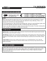
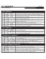
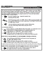
ENTERING REMOTE PROGRAM MODE
The system can lean up to 4 different remote’s. Each remote to be used MUST
be programmed together during the same sequence. For security, when a new
remote is programmed all previous remote’s are deleted. Please see remote
operation chart for information on using Second Car / Pad Lock Operations.
HOLD the program switch, the HORN will honk ONCE and the park lights will
turn on. (If the HORN does not honk repeat step 1) CONTINUE TO HOLD until
the HORN honks 5 times
Press & Release LOCK (START ON 1172) button on 1st Remote to be
Programmed for Normal Operation
If remote(s) are to be
programmed for "PADLOCK" skip and goto step 6.
Press & Release BUTTON 4 on Remote to be Programmed
for 2ND CAR OR PAD LOCK
HORN will honk 1 time to confirm remote has been
programmed (If the HORN does not honk press button again)
HORN will honk 1 time to confirm remote has been
programmed (If the HORN does not honk press button again)
PROGRAMMING REMOTE’S
Cycle the Ignition Key - ON/OFF ON/OFF ON
(Leaving the key ON)
Turn ignition key OFF to exit remote program mode when
all required remote’s have been programmed.
1 honk confirms program mode entered followed by
5 honks confirming transmitter program mode
1 -
2 -
3 -
4 -
6 -
5 -
7 -
8 -
REPEAT STEP 4 IF A SECOND REMOTE IS TO BE PROGRAMMED FOR NORMAL OPERATION
REPEAT STEP 6 IF A SECOND REMOTE IS TO BE PROGRAMMED FOR 2ND CAR / PADLOCK OPERATION
To program 2nd car operation on 2way models enter transmitter program mode and turn the # icon
on then program the transmitter to the vehicle. If the # icon is on the remote is in 2nd car operation
.