
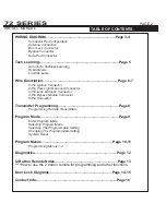
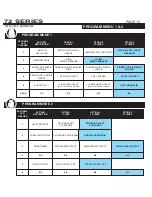
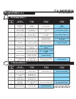


SYSTEM PROGRAMMING -
Menu 1
PAGE 4
INSTALL MANUAL
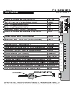
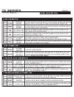
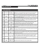
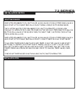
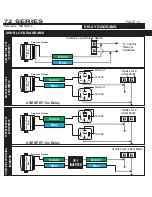
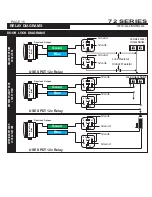
WIRE DIAGRAM
1
2
3
1
2
3
1
2
3
4
Position 1 or Position 2
GREEN
BLUE
N/A*
N/A
BLACK
WHT/VIOLET
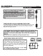
SELECTABLE PARK LIGHT OUTPUT
OUTPUT TO ACTIVATE DOOR LOCK CIRCUIT (-)
OUTPUT TO ACTIVATE DOOR UNLOCK CIRCUIT (-)
OUTPUT FOR VOLTAGE INVERTER*
N/A
GROUND FOR BYPASS MODULE
GROUND WHEN RUNNING (BYPASS TURN ON)
* THE CENTER PIN OF THE KEYLESS CONNECTOR IS LOW CURRENT AND
IS DESIGNED TO SUPPLY POWER TO DOOR LOCK MODULES (DO NOT
CONNECT TO RELAYS) OVERLOADING THIS OUTPUT WILL DAMAGE THE
MODULE!
**
FOR USE WITH COMPATIBLE BYPASS MODULES ONLY.
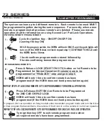
BY DEFAULT THE SYSTEM COMES WITH THE PARK
LIGHT JUMPER SET FOR POSITIVE PARK LIGHT
OUTPUT. TO CHANGE THE SYSTEM TO A NEGATIVE
PARK LIGHT OUTPUT, PLACE THE JUMPER IN THE
NEGATIVE PARK LIGHT POSITION SHOWN IN THE
DIAGRAM.
(Position 2)
*THE PARK LIGHT RELAY WILL NOT “CLICK” WHEN
SET FOR NEGATIVE PARK LIGHTS.
POSITIVE
PARK LIGHT
NEGATIVE
PARK LIGHT
72 SERIES
BYPASS MODULE DATA COMMUNICATION PORT**
*The default setting is for idatalink modules. For Fortin bypass modules power-
up the system with the Fortin module connected to the data port to set the
default to Fortin bypass module.
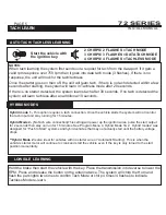
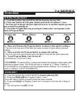
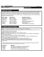
AUTO TACH/ TACHLESS LEARNING
HYBRID MODE‘S
Start the vehicle with
the ignition key.
2 CHIRPS/ 2 FLASHES = TACH MODE
NOTES:
When tach learning the system first sends out a request for tach from the data port. If it gets a
valid rpm response over 750 rpm then it goes into data tach mode (3 flashes). If there is no
response, the unit will look for the tach/tachless.
Once the starter goes on then off, the unit will learn tach, if there is no tach detected within a few
seconds after starting, the system will learn in Tachless mode after 20 seconds.
If there is no starter detected, the system learns tach after 30 seconds. If no tach is detected the
system will learn tachless after an additional 10 seconds.
Hybrid mode 1 -
This option requires a tach connection. Once the vehicle starts the system will not monitor
the tach input and stay running for 15 minutes.
Hybrid Mode 2-
(No Tach wire connection)This setting will power up the ignition wires, pulse the start output
for 2 seconds then stay on/ run for 15 minutes. See Program Menu 4, Hybrid Mode 1& 2. Hybrid mode 2 was
designed for
hybrid vehicles that may not actually start until the battery voltage
drops.
**Hybrid Mode 2
is also ideal for vehicles with no starter wire or “Automatic Starting”. This is when the
vehicle’s starter motor will continue to crank and start the vehicle even if the key is only turned to the start
position momentarily.
“Push to Start” systems and
Hold the brake then start the vehicle with the key. Place the transmission into reverse to lower the
RPM. Press and release the button on the antenna twice. The system will chirp the Horn and
flash the park lights two times to confirm Tach Mode or chirp 4 times/ 4 flashes to indicate
Tachless Mode re-learn.
LOW IDLE LEARNING
4 CHIRPS/ 4 FLASHES = TACHLESS MODE
3 CHIRPS/ 3 FLASHES = DATA TACH MODE
SYSTEM PROGRAMMING -
Menu 1
PAGE 5
INSTALL MANUAL
TACH LEARN
72 SERIES


