
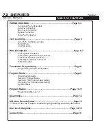
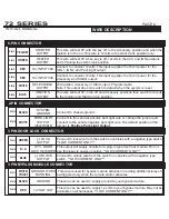
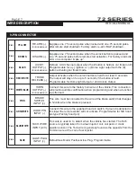
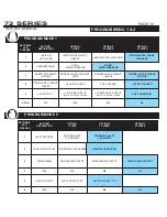
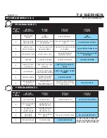

SYSTEM PROGRAMMING -
Menu 1
PAGE 12
INSTALL MANUAL
DIAGNOSTICS
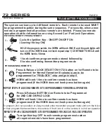
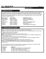
DIAGNOSTICS CHART
2 BUTTON REMOTE
INSTALLER NOTES
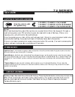
TO ENTER DIAGNOSTIC MEMORY
If the remote starter does not activate when the start button is pressed the park lights will flash a diagnostic
to indicate what shutdown input has been triggered. For example:
If the start
button is pressed the park
lights flash 3 times slowly.
Looking at the chart below this would indicate that the system is in Service Mode,
simply follow the instructions listed in the owners manual on exiting Service Mode and the remote starter
will begin to function as normal.
PARK LIGHTS STATUS LED
DIAGNOSTIC CODE
3 Slow Flashes LEDs “ON” Solid
System Is In Service Mode
4 Slow Flashes Series of 4 Flashes
Not in Reservation Mode
5 Flashes Series of 5 Flashes
Hood Open
5 Slow Flashes Series of 5 Flashes
Ignition On During Start Attempt
6 Flashes Series of 6 Flashes
Brake Pedal Shutdown
7 Flashes Series of 7 Flashes
Tach Lock-Out
8 Flashes
Series of 8 Flashes
3 Start Attempts Without Starting
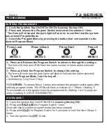
Step 1-
Turn the ignition ON then OFF. Press and release the Program Button.
Step 2-
The system will respond with three park light flashes and the HORN (optional) will honk the same
number of times as the events in memory.
****
Maximum four events, four honks****
NOTE:
If the HORN does not honk, there are no events in memory.
Step 3-
Press the Program Button once to view the last shut down code. The HORN (optional)will honk
once to confirm code one.
****
If the HORN does not honk, there are no codes in memory.****
Step 4-
The LEDs on the antenna will flash a code corresponding to a shut down trigger. Press the
Program Button again for the second code.
***
The HORN will honk twice to confirm code two three time for code three...***
Step 5-
To
Clear Diagnostic Memory.
While in Diagnostic Mode press and hold the
Program Button for five seconds. The park lights will flash and the HORN (optional)
will honk once.
****
Once diagnostic memory has 4 shutdown events in memory, the system will not record any further
shutdown events until the system memory has been cleared.****
LED Flashes Diagnostic
5 Flashes The system was shutdown by the brake switch input
6 Flashes The system was shutdown by the hood pin input
7 Flashes The system did not detect the Tach signal.
8 Flashes The system made 3 start attempts without starting
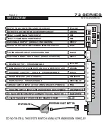
72 SERIES
SYSTEM PROGRAMMING -
Menu 1
PAGE 13
INSTALL MANUAL
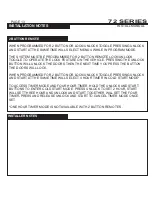
INSTALLATION NOTES
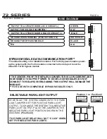
72 SERIES
WHEN PROGRAMMED FOR 2 BUTTON OR LOCK/UNLOCK TOGGLE PRESSING UNLOCK
AND START AT THE SAME TIME WILL SELECT MENU 4 WHILE IN PROGRAM MODE.
THE SYSTEM MUST BE PROGRAMMED FOR 2 BUTTON REMOTE LOCK/UNLOCK
TOGGLE TO OPERATE THE LOCK FEATURE ON THE VEHICLE. PRESSING THE UNLOCK
BUTTON WILL UNLOCK THE DOORS THEN THE NEXT TIME YOU PRESS THE BUTTON
THE DOORS WILL LOCK.
WHEN PROGRAMMED FOR 2 BUTTON OR LOCK/UNLOCK TOGGLE PRESSING UNLOCK
AND START AT THE SAME TIME WILL SELECT 4 HOUR TIMER IN COLD START MODE*.
TO ACCESS TIMER MODE AND FOUR HOUR TIMER. HOLD THE UNLOCK AND START
BUTTONS TO ENTER COLD START MODE. PRESS UNLOCK TO SET 2 HOUR, START
WILL SET THREE HOUR AND UNLOCK AND START TOGETHER WILL SET THE FOUR
TIMER
.
PRESS AND RELEASE UNLOCK AND START TO CANCEL TIMER MODE ONCE
SET.
*ONE HOUR TIMER MODE IS NOT AVAILABLE WITH 2 BUTTON REMOTE’S.