background image

9

This  heater  is  provided  with  a  properly  certified  combination 


temperature - pressure relief valve by the manufacturer.

The valve is certified by a nationally recognized testing laboratory 

that  maintains  periodic  inspection  of  production  of  listed 

equipment of materials as meeting the requirements for Relief 

Valves for Hot Water Supply Systems, ANSI Z21.22 • CSA 4.4, 

and the code requirements of ASME.

If replaced, the valve must meet the requirements of local codes, 

but not less than a combination temperature and pressure relief 

valve certified as indicated in the above paragraph.

The valve must be marked with a maximum set pressure not to 

exceed the marked hydrostatic working pressure of the water heater


 (150 psi = 1,035 kPa) and a discharge capacity not less than the 

water heater input rate as shown on the model rating plate.

for safe operation of the water heater, the relief valve must 
not be removed from its designated opening nor plugged.

The temperature-pressure relief valve must be installed directly 

into the fitting of the water heater designed for the relief valve.  

Provide tubing so that any discharge will exit only within 6 inches 

(153 mm) above an adequate drain,  or external to the building 

or structure.  Be certain that no contact is made with any live 

electrical part.  The discharge opening must not be blocked or 

reduced  in  size  under  any  circumstances.    Excessive  length, 

over 30 feet (9.14 m), or use of more than four elbows can cause 

restriction and reduce the discharge capacity of the valve.

No valve or other obstruction is to be placed between the relief valve 

and  the  tank.    Do  not  connect  tubing  directly  to  discharge  drain 

unless a 6 inch air gap is provided.  The relief valve must be allowed 

to  discharge  water  in  sufficient  quantities,  should  circumstances 

demand, to prevent bodily injury, hazard to life, or property damage.  

If the discharge pipe is not connected to a drain or other suitable 

means, the water flow may cause property damage.

The Discharge Pipe:

•  Shall not be smaller in size than the outlet pipe size of the valve,


  or have any reducing couplings or other restrictions.

•  Shall not be plugged or blocked.

•  Shall be of material listed for hot water distribution.

•  Shall be installed so as to allow complete drainage of both the 


  temperature-pressure relief valve, and the discharge pipe.

•  Shall terminate at an adequate drain or external to the building


  or structure.

•  Shall not have any shut-off valve between the relief valve and


  tank nor in the discharge pipe.

The temperature-pressure relief valve must be manually operated 

at least once a year.  Caution should be taken to ensure that (1) no 

one is in front of or around the outlet of the temperature-pressure 

relief valve discharge line, and (2) the water manually discharged 

will not cause any bodily injury or property damage because the 

water may be extremely hot.

If  after  manually  operating  the  valve,  it  fails  to  completely 

reset  and  continues  to  release  water,  immediately  close 

the  cold  water  inlet  to  the  water  heater,  follow  the  draining 

instructions, and replace the temperature-pressure relief valve 

with  a  new  one.

fillinG  the  water  heater

Never  use  this  water  heater  unless  it  is  completely  full  of 

water. To prevent damage to the tank and heating element, 

the  tank  must  be  filled  with  water.  Water  must  flow  from 

the  hot  water  faucet  before  turning  “ON”  electrical  supply 

to  the  water  heater. The  manufacturer  will  not  warrant  any 

elements  damaged  by  failure  to  follow  instructions.

To  fill  the  water  heater  with  water:

1.  Open  the  cold  water  supply  valve  to  the  water  heater.  


note: the cold water supply valve must be left open 
when  the  water  heater  is  in  use.

2.   To  ensure  complete  filling  of  the  tank,  allow  air  to  exit 

by  opening  the  nearest  hot  water  faucet.    Allow  water 

to  run  until  a  constant  flow  is  obtained.   This  will  let  air 

out  of  the  water  heater  and  the  piping.

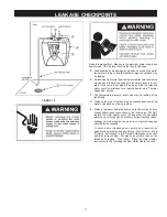
3.  Check all water piping and connections for leaks.  Repair 

as  needed.

4.  Never  alter  or  modify  the  certified  construction  of  the 

water  heater  or  its  components,  or  bypass  any  safety 

features.  Doing  so  voids  all  warranties.

Summary of Contents for 2.5 Gallon 120 volt water heater

Page 1: ... BE DIRECTED TO THE LOCAL DEALER FROM WHOM THE WATER HEATER WAS PURCHASED IF YOUARE UNSUCCESSFUL PLEASE WRITE TO THE COMPANY LISTED ON THE RATING PLATE ON THE WATER HEATER LISTED Instruction Manual RESIDENTIAL ELECTRIC 2 5 GALLON 120 VOLT WATER HEATER FOR POTABLE WATER HEATING ONLY NOT SUITABLE FOR SPACE HEATING http waterheatertimer org How to install under counter water heater html ...

Page 2: ...S Qualified Installer A qualified installer must have ability equivalent to a licensed tradesman in the fields of plumbing and electrical installation of these appliances This would include a thorough understanding of the requirements of the National Electrical Code and applicable local electrical and plumbing codes and tools necessary to confirm proper installation and operation of the water heat...

Page 3: ... GENERAL SAFETY ...

Page 4: ...ter heater INSTALLATION OR SERVICE OF THIS WATER HEATER REQUIRES ABILITY EQUIVALENT TO THAT OF A LICENSED TRADESMAN IN THE FIELD INVOLVED PLUMBING AND ELECTRICAL WORK ARE REQUIRED Examine the location to ensure the water heater complies with the Facts to Consider About the Location section in this manual 5 For California installation this water heater must be braced anchored or strapped to avoid f...

Page 5: ...abled If anyone using hot water in your home fits into one of these groups or if there is a local code or state law requiring a certain temperature water at the hot water tap then you must take special precautions In addition to using the lowest possible temperature setting that satisfies your hot water needs a means such as a mixing valve should be used at the hot water taps used by these people ...

Page 6: ...d by a leak detector or water shut off device used in conjunc tion with a piped drain pan These devices are available from some plumbing supply wholesalers and retailers and detect and react to leakage in various ways Sensors mounted in the drain pan that trigger an alarm or turn off the incoming water to the water heater when leakage is detected Sensors mounted in the drain pan that turn off the ...

Page 7: ...t against the bracket FIGURE 3A MOUNTING FLOOR 1 The floor selected must be capable of supporting double the weight of the unit when completely full of water 77 Ibs 2 The installation area must provide adequate clearances for removal of the front panel and servicing the unit 3 Place a suitable drain pan under the unit The pan must limit the water to a maximum depth of 2 1 2 inches and be 2 inches ...

Page 8: ...d systems do not allow for the expansion of heated water The water within the water heater tank expands as it is heated and increases the pressure of the water system If the relieving point of the water heater s temperature pressure relief valve is reached the valve will relieve the excess pressure The temperature pressure relief valve is not intended for the constant relief of thermal expansion T...

Page 9: ...flow may cause property damage The Discharge Pipe Shall not be smaller in size than the outlet pipe size of the valve or have any reducing couplings or other restrictions Shall not be plugged or blocked Shall be of material listed for hot water distribution Shall be installed so as to allow complete drainage of both the temperature pressure relief valve and the discharge pipe Shall terminate at an...

Page 10: ...10 WIRING DIAGRAM FIGURE 5 ...

Page 11: ...liar with the electric codes and practices or if you have any doubt even the slightest doubt in your ability to connect the wiring to this water heater obtain the service of a competent electrician Contact a local electrical contractor and or the local electric utility WATER HEATERS EQUIPPED FOR ONE VOLTAGE ONLY This water heater is equipped for one type voltage only Check the rating plate near th...

Page 12: ...r temperatures be used to avoid the risk of scalding It is further recommended in all cases that the water temperature thermostat be set for the lowest temperature which satisfies your hot water needs This will also provide the most energy efficient operation of the water heater KEEPING THE THERMOSTAT SETTING AT 120 F 49 C OR LOWER WILL REDUCE THE RISK OF SCALDS Figure 6 shows the approximate time...

Page 13: ...n the water heater this harmless bacteria is nontoxic to humans D An excess of active hydrogen in the tank This is caused by the corrosion protective action of the anode Smelly water may be eliminated or reduced in some water heater models by replacing the anode s with one of less active material and then chlorinating the water heater tank and all hot water lines Contact the local water heater sup...

Page 14: ...od sacrifices itself to protect the tank Instead of corroding the tank water ions attack and eat away the anode rod This does not affect the water s taste or color The rod must be maintained to keep the tank in operating condition NOTE Artificiallysoftenedwaterismorecorrosivebecausetheprocess substitutes sodium ions for magnesium and calcium ions The use of a water softener may decrease the life o...

Page 15: ...n or replace it 1 Turn off and unplug the water heater from the electrical outlet and follow DRAINING INSTRUCTIONS 2 Remove the front panel see the REMOVING THE FRONT PANEL section in this manual Remove the insulation pad 3 Remove the two screws from the mounting bracket see Figure 10 being careful not to drop the screws into the unit as they will be difficult to retrieve Remove bracket and set sc...

Page 16: ...or replacing the element in ELEMENT CLEANING REPLACEMENT High Limit Switch Removal and replacement 1 Turn off and unplug the heater from the electrical outlet 2 Remove the front panel see the REMOVING THE FRONT PANEL section in this manual Remove the insulation pad Remove personnel barrier 3 Remove the four wires connected to the switch taking care to note the original placement of each wire 4 Usi...

Page 17: ...ater on the side of the tank may be condensation due to the panel or insulation not being in place E Water in the water heater bottom or on the floor may be from condensation loose connections or the relief valve DO NOT replace the water heater until a full inspection of all possible water sources is made and necessary corrective steps taken Leakage from other appliances water lines or ground seep...

Page 18: ...blem Possible Cause s Corrective Action These guidelines should be utilized by a qualified service agent TROUBLESHOOTING GUIDELINES Improperly sealed hot or cold supply connection relief valve or drain valve Leakage from other appliances or water lines No power to heater High Temperature Limit Switch open Non functioning thermostat Non functioning thermostat Improper calibration Thermostat set too...

Page 19: ... number of your Water Heater will be found on the rating plate located above or adjacent to outer door WHEN ORDERING REPAIR PARTS ALWAYS GIVE THE FOLLOWING INFORMATION MODEL NUMBER SERIAL NUMBER VOLTAGE AND ELEMENT WATTAGE PART DESCRIPTION THIS IS A REPAIR PARTS LIST NOT A PACKING LIST figure 13 1 Element Gasket 2 Anode Rod 3 Element Assembly with Gasket Anode Fasteners 4 High Limit with Personnel...

Page 20: ...20 ...

Reviews: