background image

1.0 Ausschwenken des Gerätes

aus dem Gehäuse und
entfernen des Auflegers

Um die Servicearbeiten auszuführen, wird
das Gerät aus dem Gehäuse herausge-

schwenkt bzw. der Aufleger entfernt.
a) Gerät herausschwenken:

Die 2 großen Befestigungsschrauben des
Auflegers herausschrauben. Jetzt das Ge-
rät aus dem Gehäuse herausschwenken
und abstützen bzw. auf eine Seite stellen.

b) Aufleger entfernen:

Vordere Tonkopfkappe und sämtliche Be-
dienungsknöpfe abziehen. Die 8 Befesti-
gungsschrauben des Auflegers heraus-
schrauben und Aufleger entfernen.

1.0 Swinging the recorder from its case

and removing depositor

For the purpose of carrying out service work,

the unit is swung out from the case or the
depositor removed.
(a) Swinging out the recorder:

Unscrew the two large fixing screws. Now
swing out the unit from the case and
support it or place it on one side.

(b) Removing the depositor:

Pull off front sound-head cap and all con-

trol knobs. Unscrew the eight fixing
screws of the depositor and remove de-
positor.

1.0 Extraction du magnétophone hors

de son coffret et démontage
de la plaque de recouvrement

Pour l'exécution des travaux de réglage et

d'entretien, il est nécessaire d'extraire le
magnétophone hors de son coffret ou de re-
tirer la plaque de recouvrement.
a) Extraction du magnétophone:

Dégager les deux grosses vis de fixation
de la plaque de recouvrement. Sortir le
magnétophone hors de son coffret et le
poser sur une de ses faces.

b) Démontage de la plaque de recouvrement:

Retirer la coiffe avant des têtes magné-
tiques et tous les boutons de commande.
Détacher la plaque de recouvrement
après le desserrage de ses huit vis de

fixation.

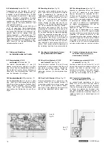
1.1 Antrieb (siehe Abb. 1)

Der Bandgeschwindigkeitswähler schaltet
gleichzeitig den Netzschalter und die zur
Bandgeschwindigkeit gehörende Entzerrung

ein. Die Umschaltung der Bandgeschwindig-
keit bewirkt ein Verstellen des Reibrades

(B), das in die jeweiligen Stufen der Motor-
rolle (A) und der Schwungmasse (C) ein-

greift.
In Stellung „Verstärker" des Bandgeschwin-
digkeitswählers wird der Motor abge-
schaltet.
Die Besonderheit des Antriebssystemes er-
möglicht den Betrieb des Gerätes in horizon-
taler und vertikaler Lage. Die nötige Voraus-

setzung dazu bringt der Aufbau der Kupplun-
gen

 Verbindung mit den Fühlhebeln. Diese

Anordnung, die bei allen Betriebsarten und

in allen Betriebsstellungen wirksam ist, wird

als „Bandzugkomparator" bezeichnet.
Zum Verständnis der Arbeitsweise des Band-

zugkomparators ist zunächst der Aufbau der

Kupplungen zu betrachten (siehe auch

Abs. 1.2). Da beide Kupplungen gleichartig
aufgebaut sind, genügt die Beschreibung
einer Kupplung.

1.1 Transport Mechanism (see Fig. 1)

The tape speed selector at the same time

switches on the mains switch and introduces
the proper equalization automatically.
Changing over the tape speed causes a
change in the position of the friction wheel
(B), which engages in the respective steps
of the motor pulley (A) and the flywheel (C).
In the position "Amplifier" of the tape speed

selector, the motor is disconnected.
The special design of the transport mecha-
nism allows the recorder to be operated in

a horizontal as well as in a vertical positipn.
This fact is due to the design of the clutches
which operate in cooperation with the sen-
sing levers. This arrangement which is effec-
tive during all modes of operation of the re-
corder, is called the "Tape Tension Com-
parator".

For the better understanding of the function-
ing of the tape tension comparator, we first
discuss the design of the clutches (see also

paragraph 1.2). Since the two clutches are
of identical design, it will suffice to describe
one of them.

1.1 Mécanisme d'entraînement (voir fig. 1 )

L'actionnement du sélecteur de vitesses pour
le choix d'une des vitesses de défilement
met en même temps le magnétophone sous

tension, c'est-à-dire enclenche le commuta-
teur du secteur et le réseau correcteur cor-

respondant à la vitesse de défilement réglée.
Le réglage de la vitesse de défilement sur la

valeur voulue déplace la roue à friction (B)
qui s'engage dans le gradin respectif de la

poulie (A) et du volant (C).
En position -Amplificateur» du sélecteur de

vitesses, le moteur d'entraînement est dé-
connecté.

Le magnétophone peut travailler aussi bien
en position horizontale qu'en position verti-
cale, grâce à la nouvelle conception du
mécanisme d'entraînement avec embrayages
spéciaux et leviers palpeurs. Ce mécanisme

extrêmement sensible, appelé -comparateur

de traction», est efficace dans toutes les
positions et pour tous les modes opératoires.
Pour comprendre plus facilement le principe
du comparateur de bande, il convient tout

d'abord d'étudier la structure des embraya-
ges (voir sous 1.2). Les deux embrayages
étant identiques, un seul sera décrit ci-
après.

Abb. 1

Fig. 1

SG 560 Royal

Summary of Contents for Royal de Luxe

Page 1: ...Schutzgeb hr DM 5...

Page 2: ...cking and Adjusting 1 6 Contr le et r glage de 8 the Wind on Clutch 8 l embrayage enrouleur 8 1 7 Checking and Adjusting the Brakes 9 1 7 Contr le et r glage des freins 9 9 9 10 11 12 12 13 13 15 16 1...

Page 3: ...nordnung die bei allen Betriebsarten und in allen Betriebsstellungen wirksam ist wird als Bandzugkomparator bezeichnet Zum Verst ndnis der Arbeitsweise des Band zugkomparators ist zun chst der Aufbau...

Page 4: ...ateur de bande et du m canisme d entrainement est expliqu e et repr sent e ci dessous en r gime Pause Start D filement acc l r avant et D filement acc l r arri re 1 11 Pause siehe Abb 1 Die auf der Ac...

Page 5: ...er M onto the thrust disk G which makes the friction within the clutch great enough to en able the clutch to transmit the entire torque provided by the friction wheel R The sens ing lever I keeps the...

Page 6: ...sing lever I controls the braking ac tion of the pay out clutch as a function of the diameter of the tape roll and thus keeps the tape tension constant When disconnecting in position Rewind the tape s...

Page 7: ...thus regulating the torque or braking action respectively of the corresponding turntable The friction within the clutches is adjusted on the basis of a tape tension measurement by adjusting the compa...

Page 8: ...clean or in a new condition and that the coupling surfaces of the pres sure disks are in a satisfactory state 1 41 Checking The tape tension comparator is checked on the basis of measurements of the...

Page 9: ...nsing lever If the tension is too strong the flap must be bent towards the sensing lever The nominal values 35 5 p during Fast Forward and Fast Rewind must result from the above adjust ments 1 5 Check...

Page 10: ...istances from the left hand friction wheel D and the right hand thrust disk M These clearances can be adjusted by bending the fla N of the adjusting plate H 1 56 Adjusting the Holding Magnet for Fast...

Page 11: ...cambrage ad quat de l ergot R 1 7 Contr le et r glage des freins 1 71 Contr le Les freins travaillent en fonction du sens de d filement de la bande magn tique et agis sent sur les plateaux presseurs...

Page 12: ...nter Lift the driving belt from the groove of the driving wheel on the digital counter Then the belt can be pulled from the groove in the turntable Install the new driving belt in re verse order 1 83...

Page 13: ...ichtige Stellung des Reibrades wie unter Abs 1 91 beschrieben zu kontrollieren 1 92 Adjusting see Fig 14 In order to adjust the friction idler A slacken the check nut B and turn the set screw C When t...

Page 14: ...st the capstan is effected in position Start After slackening of the check nut L the pressure may be increased by turning the set screw M clockwise Adjust a clearance of 0 5 mm approx 0 02 relative to...

Page 15: ...rer une bande enclencher le magn tophone et mettre le s lecteur de fonctions dans sa position Start La bande doit passer exactement entre les limites sup rieure et inf rieure des guides sans les effle...

Page 16: ...en arri re de la t te Dans la version quatre pistes ou bipiste de l unit des t tes magn tiques la t te de commande du Dia Pilot doit tre ajust e de mani re que l ar te inf rieure de son entrefer se tr...

Page 17: ...r le signal des deux voltm tres sur sa tension de sortie maximale La hauteur correcte de la t te d enregistrement est ainsi obtenue Appliquer ensuite un signal de 10 kHz environ 50 mV et le r gler sur...

Page 18: ...se of operating faults The greases and oils to be used have been listed in the UHER set of lubricants Order No 09046 2 61 Lubrification Tous les organes qui ex cutent un mouve ment de rotation sont po...

Page 19: ...4 track 56 dB 2 track Attenuation of erasure 7 1 2 ips 72 dB 1000 Hz Generator frequency 100 kHz 10 Crosstalk attenuation 60 dB mono 45 dB stereo Input microphone 0 12 mV to 70 mV max Input radio 1 2...

Page 20: ...e r t in Pfeilrichtung aus der Holzzarge heraus schwenken The Service Instruction for the model UHER SG 560 Royal also applies to the models UHER Royal de Luxe and UHER Royal de Luxe C The paragraphs...

Page 21: ...ons dans sa position Pause Le galet presseur doit se d tacher du cabestan sur un cart de 0 4 0 1 mm L embrayage enrouleur ne doit tendre la bande magn tique que faiblement D placer le s lecteur de fon...

Page 22: ...oment of the right hand clutch is adjusted by bending the actuating rod H in such a manner that the tape is only under slight tension in position Pause or in con junction with the rapid stop 2 25 R gl...

Page 23: ...7 8 15 16 ips Frequency range at 7 1 2 ips 20 20 000 Hz Frequency range at 3 3 4 ips 20 15 000 Hz Frequency range at 1 7 8 ips 20 9 000 Hz Wow and flutter at 7 1 2 ips 0 05 Wow and flutter at 3 3 4 ip...

Page 24: ...4 Ohm Sinus Dauerten 2x 10 Watt Leistungsbandbreite 20 14 000 Hz bei 1 Klirrfaktor bersprechd mpfung 60 dB Fremdspannungsabstand Pegel I bei 50 mW 64 dB Pegel II bei 50 mW 69 dB bei 10 W 75 dB bei Mi...

Page 25: ......

Page 26: ......

Reviews: