background image

Durch  das  Festhalten  der  Federwaage  wird
die  Kupplung  abgebremst  und  kommt  zum
Stillstand. Jetzt wird die Federwaage langsam
in  Richtung  des  Bandlaufes  bewegt,  bis  sich
die Kupplung wieder dreht. In diesem Zustand
zeigt die Federwaage den Aufwickelzug an.

Sollwert: 23 p ± 3 p.

Wird  der  Sollwert  nicht  erreicht,  so  ist  zu-
nächst  zu  prüfen,  ob  der  Filzring  auf  den
Kupplungsscheiben  abgenutzt  oder  ver-
schmutzt  ist.  Desgleichen  sind  die  Laufflä-
chen der Kupplungsoberteile zu reinigen. Eine
Justiermöglichkeit  für  die  Friktion  zwischen
Kupplungsscheibe  und  Kupplungsoberteil  der
rechten  Kupplung  wurde  nicht  vorgesehen
und  ist  auch  nicht  notwendig.  Falls  der
Sollwert  des  Aufwickelzuges  nicht  erreicht
wird,  kann  die  Ursache  nur  in  einer  Ver-
schmutzung  oder  Abnutzung  der  Kupplungs-
teile liegen.

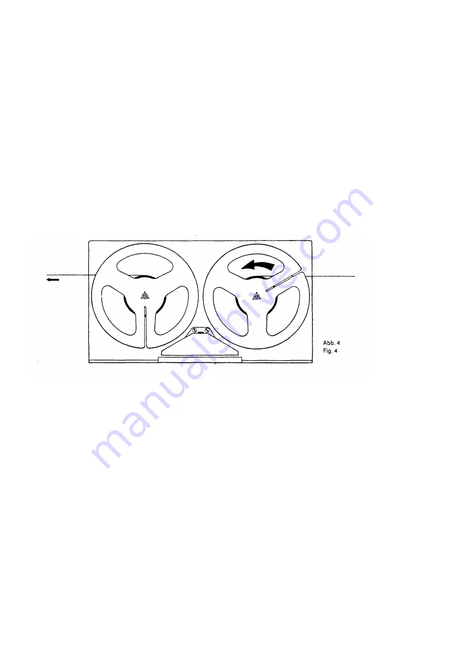
wound.  Hock  the  spring  balance  into  the
looped  free  end  of  the  tape,  switch  an  the
recorder  and  depress  the  start  key.  Hold  the
spring balance in place.
When  the  spring  balance  is  held  in  place,  the
turntable  drum 

is 

braked  down  and 

will 

come

to  a  standstill.  Now  move  the  spring  balance
slowly  in  the  moving  direction  of  the  tape  until
the  turntable  drum  starts  rotating.  At  this
moment  the  spring  balance  will  indicate  the
winding tension.

Desired value: 23 ± 3 grams

(approx. 0.8 ± 0.1 oz.)

If  the  desired  values  cannot  be  attained,  first
check whether the fett rings an the clutch disks
are  worn  or  soiled.  The  linings  an  the  Inner
side  of  the  tumtable  drums  must  also  be
cleaned.  The  right-hand  clutch  neither
possesses  nor  needs  a  means  for  adjusting
the  friction  between  the  clutch  disk  and  the
turntable  drum.  If  the  desired  value  of  the
winding  tension  cannot  be  attained,  this  can
only be due to worn or soiled clutch parts.

tion. Enclencher le magnetophone et enfoncer
la touche •Start».
Le  päse-ressort  ätant  immobilisö,  I'embrayage
est  freinä,  puis  s'arräte  complätement.
Relächer  le  päse-ressort  lentement  dans  Je
sens du däfilement de 

la 

bande, jusqu'ä ce que

I'embrayage  reprenne  son  möuvement  de
rotation.  A  cet  instant,  le  pese-ressort  indique
la traction d'enroulement.

Valeur nominale: 23 g ± 3 g

Lorsque  kette  valeur  n'est  pss  atteinte,  il  y  a
lieu  de  värifier  d'abord  si  la  bague  de  feutre
des  plateaux  d'acccuplement  est  usäe  ou
encrassäe.  Nettoyer  ensuite  la  surface  de
roulement  des  parties  supärieures  d'embray-
ages.
Une' possibilitä d'ajustage n'est pss näcessaire
-  et  n'est  pss  prävue  -  pour  la 

fric

tion  entre  le

plateau  d'accouplement  et  la  partie  supärieure
de 

I'embrayage 

droit. 

Si 

la 

traction

d'enroulement  de  la  bande  s'äcarte  de  sa
valeur  nominale,  il  ne  peut  s'agir  que  de
I'encrassage  ou  de  I'usure  des  organes  de
l'embraysge.

9.14 Ein- und Ausbau der Kupplungen

(siehe Abb. 2)

Rechte Kupplung:
Befestigungsschraube (X) des Winkels (V)


für

das Widerlager lockern. Winkel zur Seite
drehen, Wellensicherung (U) entfernen. Auf
Unterlegscheiben (T)


achten. Der Zusammen-

bau erfolgt sinngemäß. Mit Madenschraube
(Y) 0,1 mm axiales Kupplungsspiel einstellen.
Linke Kupplung:
Das  an  der  Unterseite  der  Kupplung  befind-
liche  Antriebsrad  (I)  entfernen  und  Kupp-
lungsoberteil (A) sowie Kupplungsscheibe (C)
nach  oben  abziehen.  Auf  Unterlegschelben
(B)  achten!  Der  Zusammenbau  erfolgt
sinngemäß.

2.14 Disassembly and Reassembly

of the Clutches (see Fig. 2)

Right-hand clutch:

Slacken the fastening screw (X) of the angular
abutment  strap  (V),  turn  the  strap  to  the  side
and  remove  the  circlip  (U).  Take  care  to  put
back  in  place  all  spacers  (T).  Reassemble  in
reverse  order.  Adjust  an  axial  play  of  the
clutch of 0.1 mm (approx. 0.004') by means of
the grub screw 

(Y).

Left-hand clutch:
Remove the pulley (I) from the underside of
the clutch and pull off the tumtable drum (A)
and the clutch disk (C) In upward direction.
Take care to put back in place all spacers (B)i
Reassemble in reverse order.

2.14 Montage et d6montage des embrayages

(voir fig. 2)

Embrayage droü:

Desserrer la via de fixation (X) de I'äquerre 

M.

Dätoumer  I'äquerre 

latäralement  et  retirer

la  rondelle  de  säcuritä  (U).  Velller  á  ne  pss
6garer les rondelles grower (T). 

La 

montage de

I'embrayage  s'exäcute  dans  fordre  de  suite
inverse.  A  I'aide  du  goujon 

M, 

ajuster  un  jeu

axial de 0,1 mm.
Embrayage gauche:

Retirer  la  roue  d'entrainement  (I)  ä  la  partie
infärieure de l'embrayage, puis extraire vers le
haut la partie supärieure d'embrayage (A) et le
plateau d'accouplement (C). Ne pss ägarer les

2.2 Bremsen
Die Bremsen arbeiten wartungsfrei. Eine Ein-
stellung  ist  nur  nach  Ersatz  von  Teilen  er-
forderlich.

2.2 Brakes
The  brakes  do  not  require  any  maintenance.
Readjustment  will  only  be  necessary  alter  any
parts have been replaced.

2.2 Freins
Les  freins  n'exigent  aucun  entretien.  Leur
räglage  n'est  näcessaire  qu'apräs  1'öchange
de leurs organes.

ob


5

Summary of Contents for 4000 REPORT-L

Page 1: ...Service...

Page 2: ...Contact pour la regulation de la vitesse du moteur 14 4 2 Contact muet 14 4 3 Interrupteur et selecteurde vitesses 15 4 4 Commutateur de piles 15 4 5 Interrupteur separateur 4 8 Commutateur de correct...

Page 3: ...the shaft I are driven via the belt F Each friction wheel is fitted with a conically ground rubber lining For better understanding of the functioning of the clutch K it seems necessary to explain its...

Page 4: ...n zur elektro nischen Drehzahlregelung gewonnen 1 2 Concept of the Motor The motor consists of a rotating permanent magnet stationary armature windings and a stationary cylindrical iron body which em...

Page 5: ...the power sources 1 32 Amplificateur pour les models 4200 4400 Report Stereo L amplificateur st reophonique d enregistre ment lecture est transistorise et comporte quatre etages pour chaque canal il...

Page 6: ...the start key and depress the fast forward key Upon this there must not be any frictional engagement left between the driving disk A and the tone of the friction wheel B There must be a clearance of...

Page 7: ...ou encrass e Nettoyer ensuite la surface de roulement des parties sup rieures d embray ages Une possibilit d ajustage n est pss n cessaire et n est pss pr vue pour la friction entre le plateau d acco...

Page 8: ...lge eingehalten wird Zuerst mu die Bremsrolle vom Kupplungs oberteil abheben und anschlie end die An druckrolle das Band gegen die Tonwelle dr cken 222 Adjustment see Fig 6 In the Stop position the br...

Page 9: ...Sechskantschrauben C und D Verschieben nach links vermindert nach rechts erh ht den Andruck 2 32 Adjustment see Fig 7 The adjustment made at the factory should not be changed unless the desired value...

Page 10: ...l commande La relais Stop dolt tre attir et bloquer la transport de la bande 2 42 Einstellen siehe Abb 7 Gegebenenfalls ist das Gest nge zum Stop relais zu justieren Dazu wird bei eingelegtem und gest...

Page 11: ...provoque I arr8t de la roue friction respektive 2 54 Einstellen des Vor und R cklaufes siehe Abb 8 und 9 Die Einstellung erfolgt durch Biegen der Fe der H f r Vorlauf bzw der Feder I f r R cklauf mitt...

Page 12: ...derni re a ete d reglee ou echangee apres son montage la t te magnetique doit tre demagn tisee 2 71 Pr fen der H henverstellung Die Stirnfl che des Tonkopfes mu parallel im Tonband stehen Die verschie...

Page 13: ...r une couche de vernis 2 8 Geschwindigkeitsw hler Auf unbedingte Sauberkeit der Gummilauf fl chen des Antriebsrades sowie der Lauf fl che von Motorrolle Antriebsriemen und Schwungmasse ist zu achten B...

Page 14: ...and the fast forward rewind seesaw 2 91 Echange du moteur voir fig 12 Retirer fas vis A et B debrancher las fils de raccordement du moteur C et sortir ce dernier Remonter le nouveau moteur de teile fa...

Page 15: ...points must be lubricated with a non gumming multi purpose grease after approximately 500 hours of operation in any event avoid a too generous use of lubricants since surplus grease or oil may reach...

Page 16: ...ew A and pivot the mounting angle B Then tighten the screw Q 4 12 R glage voir fig 13 Le reglage s op re apres le desserrage de la vis A par le deplacement de I querre de retenue B Resserrer ensuite l...

Page 17: ...4400 Report Stereo Le contact K9 K5 est actionne lors de lamise en piace de I accumulateur ou du bloc sec teur chargeur dans le casier des piles 4 41 Pr fen Der Kontakt K 9 bzw K 5 mu bei eingeleg te...

Page 18: ...erneath the contact springs When the contact is open the clearance between the contact points must be approximately 0 1 mm 0 004 4 62 Reglage Le contact rei a doit demeurer ferm lors que son relais n...

Page 19: ...ors respecter las prescriptions eta blies par les constructeurs de transistors 5 1 Elektrische Einstellungen und Me werte Das beiliegende Schaltbild enth lt auf seiner R ckseite die entsprechenden Reg...

Page 20: ...cps 1 000 cps 1 250 cps 1 600 cps 2 000 cps 2 500 cps 3 150 cps 4 000 cps 5 000 cps 6 300 cps 8 000 cps 10 000 cps 12 500 cps 18 000 cps 20 000 cps 1 000 cps en 19 05 cm s 1000 Hz 40 Hz 63 Hz 80 Hz 10...

Page 21: ...cps and adjust the output voltage of the audio oscillator in such a manner that the connected VTVM reads apprpximately 1 0 volt Thereafter do not vary the Output voltage of the oscillator any more 5 4...

Page 22: ...e is recom mended Thread a UHER Test Tape turn the recording level control to its extreme anticlockwise position and erase both tracks Connect an audio frequency millivoltmeter across the contacts 3 a...

Reviews: