EN
EN
C -INSTALLATION OF YOUR COOLER.
C -INSTALLATION OF YOUR COOLER.
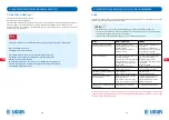
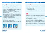
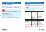
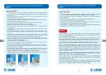
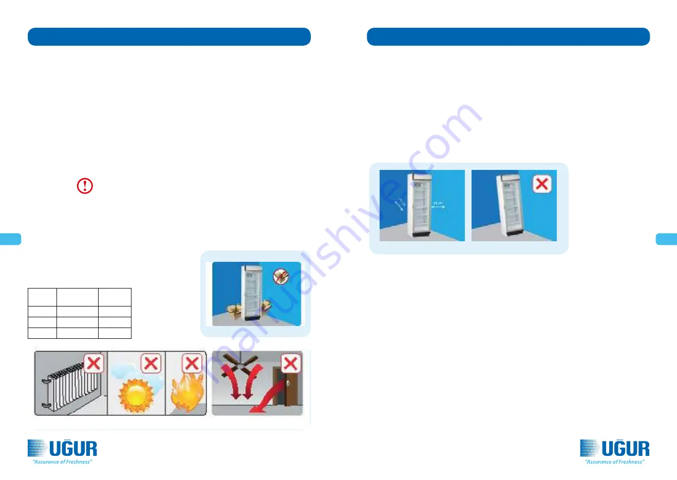
Selecting the place of installation
The operating environment of the product is very important for the smooth operation of your product. While selecting
the operating environment,
• Do not place your product exposed to outdoor environment (on the street, avenue etc.)
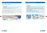
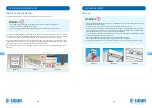
• Be careful for not obstructing lower shutter of the product with materials such as cardboard, box etc. for a proper
cooling. (Picture 4)
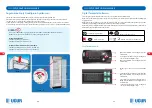
• Place the product at least one (1) meter away from heat resources (ex: stove, radiator, electric heater etc.) (Picture 5)
• Do not place it opposite of the air conditioner chutes, under fans and direct door and window openings. (Picture 6)
• Do not expose to direct sunlight. Operation ratio will increase if sunlight comes to the cooler’s glass. That means an
increase in the energy consumption.
• Air intake and outlet must absolutely be fluent and free for proper operation of the compressor section of your pro-
duct.
• While approaching your product to the wall, be careful that there is a gap of 150 mm (15 cm) between the wall and
back of your cooler.
WARNING!
In very humid environments, ensure that floor and wall of the place where the cooler is located, is not affected by water;
against discharge water overflow danger.
In installations performed by Authorized Uğur Service, Authorized Uğur Service shall inform the consumer on the suitab-
le place for installation and make suggestion, but the consumer shall give the final decision on where the installation will
be made. This process shall also be stated on the relevant installation form by Authorized Uğur Service. In case of any loss
arising from the place of installation of the product according to the final decision given by the consumer, all responsibi-
lity related to such loss shall belong to the consumer.
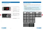
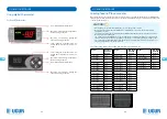
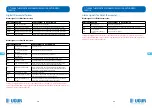
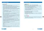
Your product gives the best cooling performance according to the
climate condition under the conditions given below. Therefore, be
careful that the temperature of the environment where your cooler
will be operated, is at these levels.
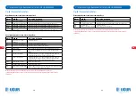
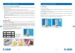
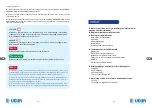
Positioning
Possible placement positions:
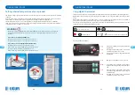
1- In a way that the back side alone is opposite to the wall; be careful that there is a gap of 150 mm (15 cm) between
the wall and your cooler. (Picture 7)
2- In a way that is place to a corner; when you place to a corner, leave a gap of 150 mm (15 cm) behind. You can lean the
side corresponding to the corner, to the wall.
The most important point to be considered in all cases of product placement is not to obstruct ventilation of the
compressor assembly.
Without expose your product to any slope, place and operate it in a manner that it is on its feet or wheels. (Picture 8)
The freer the compressor assembly ventilation is, the better the device will run.
Climate
Class
Tempera-
ture Range
Humidity
Class 3
16 °C to 25 °C %60 Rh
Class 4
16 °C to 30 °C %55 Rh
Class 5
16 °C to 40 °C %45 Rh
Climate Class of your
product is indicated
on the technical
specification label on
the product.
Picture 7
Picture 4
Picture 5
Picture 6
Picture 8
44
45
Summary of Contents for USS 60 DTKL
Page 92: ...RU RU B B EN23953 2 U ur So utma A 182 183...
Page 95: ...RU RU C 10 10 16 12 11 D 23 1 220 240 50 13 0 1 1 14 15 10 11 12 13 14 15 188 189...
Page 98: ...RU RU E D 18 U ur So utma A 2 U ur 18 194 195...
Page 99: ...RU RU F U ur U ur U ur U ur U ur U ur D 65 196 197...
Page 102: ...AR AR PCT PCB CFC R600a R134a R404a R290 10 U UR SO UTMA A 202 203...
Page 103: ...AR AR 204 205...
Page 104: ...AR AR 1 50 240 220 2 3 1 2 20 24 WEEE EC 2002 96 WEEE 1 2 3 206 207...
Page 105: ...AR AR R290 R600a 208 209...
Page 106: ...AR AR EN23953 2 U ur So utma A 210 211...
Page 107: ...AR AR 4 5 1 6 15 150 7 51 051 1 51 051 2 8 3 25 16 60 4 30 16 55 5 40 16 45 7 4 5 6 8 212 213...
Page 109: ...AR AR 10 61 01 21 11 10 11 12 23 1 13 50 240 220 15 14 1 1 0 13 14 15 216 217...
Page 112: ...AR AR 81 2 81 222 223...
Page 113: ...AR AR 20 65 224 225...
Page 115: ......

