When measuring resistance, be sure you have good contact between
the test leads and the circuit. Dirt, oil, solder flux, or other foreign
matter alters the reading value.
To measure resistance, follow these steps:
1. Insert the test leads into the meter, and turn off the power to the
circuit under test. Voltage, from any source, across the circuit will
cause an erroneous reading.
2. Set the rotary dial to the “
Re s i s t a n ce / C o n t i n u i t y
” function, then
turn on th power to the meter. The meter defaults to the resistance
measurement mode.
3. Touch the test probes to the test points, and read the display.
The meter beeps as it seeks the correct range to measure the
circuit resistance.
Note:
•
During continuity or resistance checks, polarity does not matter.
•
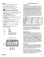
It may test circuits to use the manual range mode to test circuits
that are susceptible to damage at low voltages/currents. See
the table to determine which range is best suited to your circuit.
Continuity Test Mode
Use this mode to make quick checks for continuity of electrical circuits,
such as wiring, speaker cables, connections, switches or relays. In the
continuity mode, an audible tone sounds when the value measured is
approximately 50
Ω
or less.
To test for continuity, follow these steps:
1. Set the rotary dial to the “
Ohms/Continuity
” function.
2. Press the “
Ω
/
“ push-button to bring the “ “ symbol up
on the top of the display, indicating that the continuity mode has
been selected . The range is preset to the 400
Ω
s cale and can not
be changed.
3. Place one probe to each side of the circuit to be tested. If
approximately 50
Ω
or less resistance is in the circuit, the meter
sounds a continuous tone.
Diode Test Mode
The diode test function allows you to check diodes, transistors and other
semi-conductor devices for open, shorts and normal operation.
CAUTION!
Never connect the test leads to a source of voltage when the diode test
function is selected.
Diodes and other P/N junction devices, easily allow current flow in one
direction and prevent current flow in the other direction. When a diode
is forward biased, it allows current to flow. When it’s reverse biased it
prevents current flow.
Your meter is designed to apply enough voltage in the forward biased
direction to allow current flow. All diodes use up or “drop” a small
amount of the supplied voltage when they are forward biased, and drop
nearly all of the supplied voltage when they are reverse biased. The
voltage drop of the diode under test is displayed on the meter when it is
forward biased. This is normally around 0.4 V for germanium diodes
and 0.6 V for silicon diodes. When the diode is reverse biased, the
meter should indicate “.
OFL
”.
Determine the condition of semiconductor devices as follows:
1. Select the diode test function on your rotary dial.
2. Connect the red test lead to the anode side of the diode, and the
black to the other. A black band is normally printed around the
end of the side of a diode.
3. Note the displayed value.
4. Reverse the red and black test leads and again note the
displayed value.
5. If the digital reading in the first (forward biased) direction
indicates some measurable value, and the reading in the reversed
direction shows an overload “.
OFL
”, the diode is good.
6. If the displayed value is low or measurable in both directions, the
diode is probably shorted.
7. If the display indicated an overload “.
OFL
” in both directions, the
diode is probably open. Some diodes require a higher biasing
voltage than this meter supplies. See UEi’s catalog to purchase an
economical, high-power diode test lead adapter set if necessary.
Measuring Current (amps)
CAUTION!
The current functions are protected by 250 volt rated fuses. To avoid
damage to the instrument, do not measure current sources with open
circuit voltages greater than 250 volts DC or AC.
Note:
When taking current measurements, this meter must be
connected in series with the circuit (or circuit element) under test.
Never connect the test leads across a voltage source while the rotary
dial is set to amps. This can cause damage to the circuit under test
or this meter.
The low amperage measurement functions share the test probe port
with the volt and ohm measurement.
DO NOT
turn the rotary dial to the
mA
or
µA
position until the circuit is
prepared for current measurements as described below.
To measure current, you must break the circuit under test and make
the meter part of the circuit. Two connection points are created when
a circuit is broken. On one side is the power source and the other is
the load. Connect the two leads in the circuit at the points created by
this break.
When measuring alternating current, any waveform other than a
sinusoidal wave will have inherent measurement error.
DM400-MAN
P. 5

