background image


24 


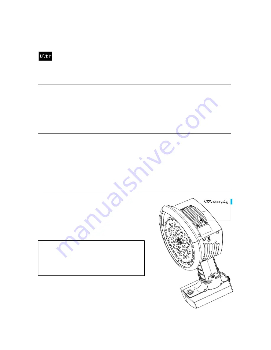
Image 12. 

The location of the USB cover 

plug. 

4.8 Filters


Press the filter button on the top right corner of the camera’s screen to switch 

between different filters. The available filters depend on the camera’s application 

mode, you can choose to activate the relevant optimal filters for finding leaks of 

partial discharges,For more information on the filters and optimization, see 

section 5.1.1 as well 

as 5.2.1

.


4.9 Real-time analysis


Real-

time analysis results are shown at the top of the camera’s screen. This includes the dB levels 

from the strongest source, the location of the sound source is shown with a crosshair as well as 
some analytics for the sound source. For details, see 

section 5: Application - specific 

features


4.10 Cloud upload 


When connected to the Internet via WiFi, the UltraView will automatically upload any snapshots on 
the device to the Cloud as long as 

Upload snapshots

 is turned on under 

Snapshot browser 

(section 4.4: Snapshot Browser)

. Snapshot upload can also be triggered manually, if the 

automatic snapshot upload is turned off. Next to the 

Snapshot Browser

 button, the number of 

snapshots currently on the device is shown. Two dots next to the number indicate that snapshots 
are currently being uploaded to the cloud. 


4.11 USB export 


Snapshots in the UltraView can be exported to a USB 
flash drive. Open the cover on top of the UltraView 
(

Image 12

) and insert the memory stick in the USB 

port. Check that the orientation of the memory stick 
and the port is correct before inserting the stick. 


The UltraView will recognize the inserted flash drive 
and ask if you want to transfer snapshots to the USB 
device. If you press Yes, the transfer will begin. During 
the transfer, the progress will be displayed, and the 
transfer can be aborted by pressing the Stop button. 
Snapshots already transferred to the USB flash drive 


!! NOTE: USE ONLY THE USB FLASH DRIVES 

PROVIDED WITH THE ULTRAVIEW. OTHER 

FLASH DRIVES ARE NOT GUARANTEED TO 
WORK AND MAY LEAD TO LOSS OF DATA!! 


Summary of Contents for ULTRAVIEW

Page 1: ...1 UE SYSTEMS INC ULTRAVIEW MANUAL ...

Page 2: ... Charging Tracer external battery 3 1 2 Charging the RRC2040 external battery 3 2 Startup 3 2 1 Startup with Tracer external battery 3 2 2 Startup with RRC2040 external battery 3 3 Device setup wizard 3 3 1 Device registration 3 4 Shutdown 3 4 1 Shutdown with Tracer external battery 3 4 2 Shutdown with RRC2040 external battery 4 1 Heatmap 4 2 Take a snapshot 4 3 Record a video 4 4 Snapshot browser...

Page 3: ...SB export 5 1 Compressed air leak detection 5 1 1 Filters 5 1 2 Distance 5 1 3 Air mode specific settings Leak unit Currency Energy cost Env temp Rel humidity Leak corr Specific power 5 2 Partial discharge detection 5 2 1 Filters 5 2 2 Distance 6 1 General usage 6 2 Locating sound sources 6 3 Reflections 6 4 Distance 9 1 Storage 9 2 Cleaning 9 3 Visual and or permanent damage 5 APPLICATION SPECIFI...

Page 4: ...CIFICALLY DISCLAIMS ANY WARRANTY OF MERCHANTABILITY OR FITNESS FOR A PARTICULAR PURPOSE WITH RESPECT TO THE PRODUCT AND DOCUMENTATION 1 2 Compliance We caution the user that changes or modifications not expressly approved by the party responsible for compliance could void the user s authority to operate the equipment Note This equipment has been tested and found to comply with the limits for a Cla...

Page 5: ...Country of origin Company name and Approval markings The electronic ID label or e label containing all the regulatory information is the primary ID plate of the UltraView The e label is available from the UltraView user interface To open the e label press the Settings icon and choose Device info ISED The ISED certification label is a word mark consisting of the Company Number CN and the Unique Pro...

Page 6: ...r with unseparated household waste but must be collected separately For this purpose all local authorities have established collection schemes under which residents can dispose of waste electrical and electronic equipment at a recycling center or other collection points or WEEE will be collected directly from households More detailed information is available from the technical administration of th...

Page 7: ...rray and the USB port from any kind of foreign objects dust or liquids Charge the battery only when disconnected from the UltraView The UltraView is not intended to be used while the batteries are charging Charge the batteries only when disconnected Charge the battery at temperatures between 0 C and 40 C 32 F to 104 F Do not leave the charging battery unattended Do not expose the batteries to flam...

Page 8: ...2 m 6 6 ft Battery charger Tracer Input 100 to 240 VAC 50 60Hz 1 3 to 1 5 A Max output 13 8 to 14 6VDC 4 0 A depends on the charger provided see the documentation or the ID plate of the charger USER INTERFACE AND DISPLAY Display Size 5 in 800x480 Colour 24 bit RGB Brightness 1000 cd m2 adjustable Input device Resistive touchscreen Power on indicator Red LED Image resolution 800x480 Video frame rat...

Page 9: ...packaging consists of 1 UltraView 2 Battery 3 Battery cable 4 Charger with a detachable mains cable 5 Carrying bag 6 Mass storage 7 Shoulder strap 2 4 Camera parts 1 Video Camera 2 Microphone Array 3 LCD Screen 4 Battery Cover 5 Battery Housing or Battery Cable with the Tracer external battery Camera side connector 6 Power LED 7 Mass Storage Port 8 Top Heatsink 9 Right Side Heat Sink 10 Left Side ...

Page 10: ...orce will affect the durability of the touch screen The status of the internal power supply unit is indicated by the power LED item 6 in Image 2 which turns red when the power is on While the power is on the UltraView dissipates heat through the three heatsinks items 8 9 and 10 in Image 2 that are located on both sides and the top of the camera While operating the UltraView the heat sinks must be ...

Page 11: ...tteries 2 5 2 RRC2040 EXTERNAL BATTERY CHARGER The RRC2040 charger has two parts the charger unit and the power supply The charger unit has connectors for the battery in the charging bay and a DC barrel input for power supply The power supply has universal mains input where the power cable can be chosen depending on the region 1 2 3 4 5 0 2 0 3 0 1 1 Power button 2 Battery cover 3 Fixing screw 4 B...

Page 12: ...iFePO4 chemistry batteries The charger has a universal single phase mains input a status LED and a charging output The charger is provided with a mains power cable including a plug compatible for your regional mains output For charging the battery the charger has a DC barrel plug at the end of the output cord Do not use any chargers other than UE Systems approved chargers 2 6 Spare parts and acces...

Page 13: ...3 1 1 CHARGING THE RRC2040 BATTERY Before using the batteries remember to charge them first To fully charge an empty RRC2040 battery usually takes about 2 hours Please note that the battery should be charged at temperatures between 0 C and 40 C 32 F to 104 F A new RRC2040 battery used in optimal environmental conditions yields over 2 5 hours of usage The RRC2040 batteries and the charger are deliv...

Page 14: ...d in optimal environment conditions yields up to 7 hours of usage This depends on multiple variables which may decrease the usage time These are the cell temperatures the load and the age cycles of the battery The Tracer battery and the charger are delivered with the UltraView Only use the provided battery charger 1 Disconnect the battery cable from the battery output connector item 1 in Image 5 f...

Page 15: ... need to attach the battery housing to the UltraView please follow the instructions below and see Image 6 After you have attached the battery housing to the UltraView by open the lid item 3 in Image 7 by turning the knob of the battery housing counterclockwise and insert the battery in to the battery housing with the connectors at the front and the charge gauge item 2 in Image 7 facing upwards Ens...

Page 16: ...st 45 minutes so the internal backup batteries are charged fully If you wish to attach the wrist lanyard that comes with the camera in the battery housing you can find the point of attachment on top of the battery housing lid Image 7 Inserting the RRC2040 battery Image 6 Attaching the RRC2040 battery housing 1 Unscrew and remove the lowest screw of the camera handle Tool 2 5 mm Hex socket screwdri...

Page 17: ...e power is on the red Power LED is lit The system starts after approximately 10 to 15 seconds The UE Systems logo will appear on the screen When the system setup is complete the UltraView s interface will start automatically and you are ready to make sound visible NOTE Hold the UltraView firmly by the handle The UltraView has internal system backup batteries which are charged by the main battery w...

Page 18: ...by disconnecting the battery power and waiting until the camera s power LED turns off If the shutdown takes more than 5 to 10 minutes after disconnecting the battery contact UE Systems for service 3 4 2 SHUTDOWN WITH TRACER EXTERNAL BATTERY To turn off the UltraView simply disconnect the battery connector from the UltraView 1 Hold the battery cable connector by the lock ring and pull it outwards T...

Page 19: ...m blue to red The center of the sound sources is shown with red while the color gradually changes via yellow green and cyan to blue outwards from the center of the sound source The location color mode is active in the Power application mode The strength color mode Image 11 shows each sound source with a single color according to the intensity of the sound source The strength color mode is active i...

Page 20: ... case you use the camera to photograph people remember to ask consent before capturing images 4 3 Record a video Press the Video Recording button on the right hand side of the Snapshot button to start recording Note that the video length is limited to 5 minutes To stop recording tap the video recording button again After you have finished recording you can enter additional information as when taki...

Page 21: ...sible settings are listed below 4 6 1 SCREEN BRIGHTNESS The brightness of the display can be adjusted by pressing the Brightness button This is useful to make the display readable under different lighting conditions indoors outdoors 4 6 2 SINGLE SOURCE MULTI SOURCE MODE Press the Single source Multi source button to toggle between the two modes In single source mode the NL Camera shows only the so...

Page 22: ...the WiFi access point Once you find and select the desired network you will be asked to enter the WiFi password Please note that only secure non public WiFi networks are supported The camera accepts WiFi networks that require password input not networks that require both a username and password An icon representing the WiFi connection status and strength is shown to the right of the settings butto...

Page 23: ... default value by choosing Reset settings Please note that doing a settings reset will not remove any snapshots revert to any previous software version or remove the device registration Remove all data All user data and settings can be removed from the device by pressing Remove all data The snapshots and device registration will be removed and the camera can then be registered with a new user Plea...

Page 24: ...apshots is turned on under Snapshot browser section 4 4 Snapshot Browser Snapshot upload can also be triggered manually if the automatic snapshot upload is turned off Next to the Snapshot Browser button the number of snapshots currently on the device is shown Two dots next to the number indicate that snapshots are currently being uploaded to the cloud 4 11 USB export Snapshots in the UltraView can...

Page 25: ...estimating the size of compressed air leaks and partial discharge detection locating and analyzing partial discharges in power grids The features specific to these two applications are described below 5 1 Compressed air leak detection The UltraView detects compressed air leaks based on the sound the leak emits The different filters available on the UltraView filter out background noise and can dam...

Page 26: ...stimate The available options are l min litres per minute and CFM cubic feet per minute CURRENCY Select the currency for the leak cost estimate from the available options ENERGY COST For the camera to estimate the cost of compressed air leaks you must enter the energy cost This usually means the local price per kWh of electricity Please note that if the currency is changed the energy cost must be ...

Page 27: ...ode you can choose to activate the relevant optimal filters for finding leaks of partial discharges Norm 10 to 30 kHz The best alternative for all cases with little background noise Offers the best detection distance High 20 to 30 kHz Offers good detection distance while filtering out most background noise sources Ultr 30 to 65 kHz Effectively filters out background noise at the expense of reduced...

Page 28: ... over your shoulder to free your hands for using the UltraView Image 13 Always put the UltraView inside the carrying bag when you need both hands for other tasks such as climbing ladders Ensure that the camera is placed in such a way inside the bag that it does not fall out 6 2 Locating sound sources In the single source mode the UltraView will always show the strongest sound source in the field o...

Page 29: ...source actually is It is often useful to take snapshots of interesting sound sources from several different directions The exact location of the source is easier to determine when viewed from different angles Sound sources can also be directional meaning that the sound level will differ depending on the direction 6 3 Reflections The UltraView can sometimes show reflections of sound sources To tell...

Page 30: ...nimum recommended sound source distance for the UltraView is approximately 0 3 meters 1 0 ft If the distance is shorter than this the location of sound sources will not be accurately displayed In addition the optical camera will not be focused on such short distances There is no specific upper limit for the distance at which the UltraView can be used In practical cases the distance is often limite...

Page 31: ...the cloud service you must first register as user and register the device to the cloud service Device registration under 4 6 1 Network settings To see further instructions please click the question mark icon when you view a specific snapshot in the Cloud 8 MAINTENANCE The intended usage conditions and instructions are described in this user manual Please NOTE DO NOT TRY TO REPAIR OR OPEN THE ENCLO...

Page 32: ...ntact UE Systems for the cleaning of the microphone array as this part is sensitive to damage However if you decide to clean the microphone array yourself you can use indirect low pressure air from a distance to blow particles away from the conical holes of the microphones If this does not work and the microphone array is still dirty contact UE Systems UE Systems is not responsible for any damage ...

Page 33: ...33 Need further support Want information regarding products or training CONTACT UE Systems Inc 14 Hayes Street Elmsford NY 10523 USA T 914 592 1220 E info uesystems com W www uesystems com ...

Reviews: