


TOBY-L2 and MPCI-L2 series - System Integration Manual
UBX-13004618 - R28
System description
Page 51 of 164
AT+UPSV=0: power saving disabled, fixed active-mode
The module does not enter low power idle-mode and the UART interface is enabled (data can be sent
and received): the CTS line is always held in the ON state after UART initialization. This is the default
configuration.
AT+UPSV=1: power saving enabled, cyclic idle/active-mode
When the AT+UPSV=1 command is issued by the DTE, the UART is disabled after the timeout set by
the second parameter of the +UPSV AT command (for more details see u-blox AT commands
Manual
Afterwards, the UART is enabled again, and the module does not enter low power idle-mode, as
following:
Periodically, for paging reception (see section
) or other activities, to temporarily receive or
send data over the UART, e.g. data buffered by the DTE with HW flow control enabled will be
correctly received
If the module needs to transmit some data (e.g. URC), the UART is temporarily enabled to send
data
If the DTE send data with HW flow control disabled, the first character sent causes the UART and
module wake-up after ~5 ms: recognition of subsequent characters is guaranteed only after the
complete wake-up (see the following subsection “wake up via data reception”)
The module automatically enters the low power idle-mode whenever possible but it wakes up to
active-mode according to the UART periodic wake up so that the module cyclically enters the low
power idle-mode and the active-mode. Additionally, the module wakes up to active-mode according to
any required activity related to the network (e.g. for the periodic paging reception described in section
, or for any other required RF Tx / Rx) or any other required activity related to module functions
/ interfaces (including the UART itself).
When the UART interface is enabled, data can be received. When a character is received, it forces the
UART interface to stay enabled for a longer time and it forces the module to stay in the active-mode
for a longer time, according to the timeout configured by the second parameter of the +UPSV AT
command. The timeout can be set from 40 2G-frames (i.e. 40 x 4.615 ms = 184 ms) up to
65000 2G-frames (i.e. 65000 x 4.615 ms = 300 s). Default value is 2000 2G-frames
(i.e. 2000 x 4.615 ms = 9.2 s). Every subsequent character received during the active-mode, resets and
restarts the timer; hence the active-mode duration can be extended indefinitely.
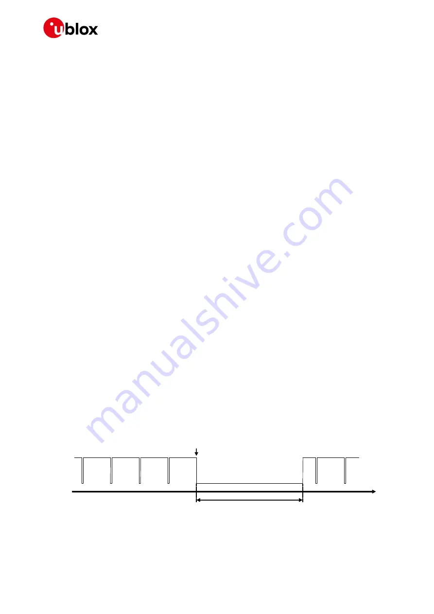
The CTS output line is driven to the ON or OFF state when the module is either able or not able to
accept data from the DTE over the UART:
illustrates the CTS output line toggling due to
paging reception and data received over the UART, with AT+UPSV=1 configuration.
time [s]
~9.2 s (default)
Data input
CTS ON
CTS OFF
Figure 23: CTS output pin indicates when module’s UART is enabled (CTS = ON = low level) or disabled (CTS = OFF = high
level)


