


LISA-U1 series - System Integration Manual
3G.G2-HW-10002-3
Preliminary
System description
Page 58 of 125
LISA-U1 series
VBUS
D+
D-
GND
18
VUSB_DET
27
USB_D+
26
USB_D-
GND
C1
USB DEVICE
CONNECTOR
D1
D2
D3
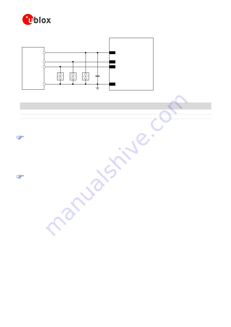
Figure 30: USB Interface application circuit
Reference
Description
Part Number - Manufacturer
D1, D2, D3
Very Low Capacitance ESD Protection
PESD0402-140 - Tyco Electronics
C2
100 nF Capacitor Ceramic X7R 0402 10% 16 V
GRM155R61A104KA01 - Murata
Table 22: Component for USB application circuit
If the USB interface is not connected to the application processor, it is highly recommended to provide
direct access to the
VUSB_DET
,
USB_D+
,
USB_D-
lines for execution of firmware upgrade over USB
and for debug purpose: testpoints can be added on the lines to accommodate the access. Otherwise, if
the USB interface is connected to the application processor, it is highly recommended to provide direct
access to the
RxD
,
TxD
,
CTS
and
RTS
lines for execution of firmware upgrade over UART and for debug
purpose. In both cases, provide as well access to
RESET_N
pin, or to the
PWR_ON
pin, or enable the
DC supply connected to the
VCC
pin to start the module firmware upgrade (see
Firmware Update
Application Note
If the USB interface is not used, the
USB_D+
,
USB_D-
and
VUSB_DET
pins can be left unconnected,
but it is highly recommended to provide direct access to the lines for execution of firmware upgrade and
for debug purpose.
1.9.4
SPI interface
SPI is a master-slave protocol: the module runs as an SPI slave, i.e. it accepts AT commands on its SPI interface
without specific configuration. The SPI-compatible synchronous serial interface cannot be used for FW upgrade.
The standard 3-wire SPI interface includes two signals to transmit and receive data (
SPI_MOSI
and
SPI_MISO
)
and a clock signal (
SPI_SCLK
).
LISA-U1 series modules provide two handshake signals (
SPI_MRDY
and
SPI_SRDY
), added to the standard 3-
wire SPI interface, implementing the 5-wire Inter Processor Communication (IPC) interface.
The purpose of the IPC interface is to achieve high speed communication (up to 26 Mb/s) between two
processors following the same IPC specifications: the module baseband processor and an external processor.
High speed communication is possible only if both sides follow the same Inter Processor Communication (IPC)
specifications.


