background image

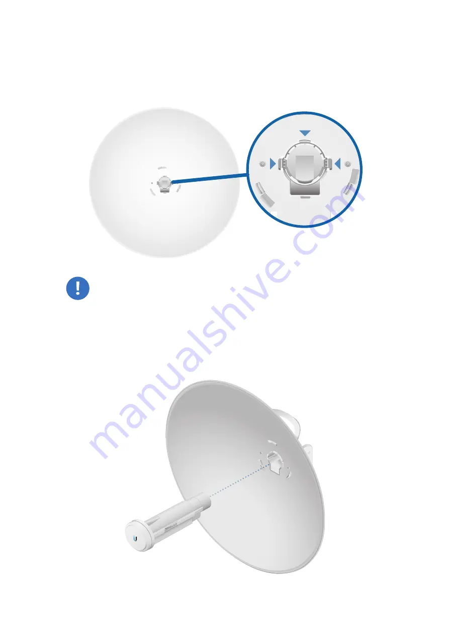
4.  View the

 Dish


Reflector

 from the front. Ensure that the 

three hooks (indicated below) of the 

Rear Housing

 are 

fully engaged with the inner wall of the 

Dish Reflector

 and 

locked into place.

IMPORTANT:

 Before proceeding, lightly pull the 

Rear 

Housing

 to confirm that it is locked into place. 

5.  Attach the 

Antenna Feed

.

a. 

Insert the 

Antenna Feed

 into the 

Rear Housing

, and push 

until it locks into place with a click.

Summary of Contents for PowerBeam airMAX AC Gen2 PBE-5AC-Gen2

Page 1: ...5 GHz High Performance airMAX ac Bridge Model PBE 5AC Gen2...

Page 2: ...Performance airMAX ac Bridge Model PBE 5AC Gen2 Flange Nuts Qty 2 Gigabit PoE 24V 0 5A with Mounting Bracket Power Cord Quick Start Guide TERMS OF USE Ubiquiti radio devices must be professionally ins...

Page 3: ...nts and destructive ESD events with industrial grade shielded Ethernet cable from Ubiquiti Networks For more details visit www ubnt com toughcable Surge protection should be used for all outdoor insta...

Page 4: ...Overview Bottom View Technology Cable Door Rear Housing Antenna Feed Ethernet Port Release Button Slot Adjustment Bracket Release Button Dish Reflector Alignment Pins Reset Button Carrying Handle Lift...

Page 5: ...ed into place If you need to remove the Antenna Feed you must depress the Release button first LEDs Power The Power LED will light blue when the device is connected to a power source Ethernet The Ethe...

Page 6: ...tdoors with the Dish Reflector installed provides directional outdoor coverage gain is reflector dependent The PowerBeam mounted outdoors without the Dish Reflector installed provides outdoor to indoo...

Page 7: ...Bracket counterclockwise until the alignment holes in the dish and bracket align with each other 2 Remove the Antenna Feed from the Rear Housing a Push in the sides of the Cable Door and detach it fro...

Page 8: ...to the Adjustment Bracket Note In high wind environments you can add support with additional hardware not included 1 Using the four holes in the Adjustment Bracket as a template drill four holes into...

Page 9: ...g are fully engaged with the inner wall of the Dish Reflector and locked into place IMPORTANT Before proceeding lightly pull the Rear Housing to confirm that it is locked into place 5 Attach the Anten...

Page 10: ...eed to ensure that it is locked into place and the Release Button is fully engaged Release Button Bottom View 6 Connect an Ethernet cable to the Ethernet Port of the Antenna Feed Then re attach the Ca...

Page 11: ...th its clamps facing you and the Elevation Indicators towards the top b Insert the two Long Carriage Bolts through the holes of the Mounting Bracket c Slide the hole of the Pole Clamp over one bolt of...

Page 12: ...the Mounting Bracket against the pole b Slide the slot of the Pole Clamp over the adjacent Carriage Bolt c Tighten the Flange Nuts of the bolts to 25 N m to secure the Mounting Bracket to the pole 25...

Page 13: ...and the two pivot pins on the Mounting Bracket Place the Reflector Dish with the attached Mounting Bracket onto the pivot pins ensuring that they fit securely inside of the slots Pivot Pin one on each...

Page 14: ...10 Install the four Hex Bolts with Washers into the Mounting Bracket Do not tighten the four Hex Bolts completely...

Page 15: ...11 Adjust the elevation angle a Pivot the antenna until the Elevation Indicator shows the desired elevation angle b Tighten the four Hex Bolts completely 20 20 Elevation Indicator...

Page 16: ...onnect the Ethernet cable from the PowerBeam s Ethernet port to the POE port of the Gigabit PoE adapter 2 Connect an Ethernet cable from your LAN to the adapter s LAN port 3 Connect the Power Cord to...

Page 17: ...PowerBeam If necessary you can power cycle the PowerBeam to re enable its Wi Fi Proceed to the appropriate instructions UNMS App 1 Download the UNMS app from the App Store iOS or Google Play Android...

Page 18: ...5 Tap Connect on the Login screen 6 Select your Country and tap Done 7 Customize your settings as needed...

Page 19: ...elect your Country and Language You must agree to the Terms of Use to use the product Click Login Note The Country setting for U S product versions is restricted to a choice of Canada Puerto Rico or t...

Page 20: ...er s responsibility to make sure the device is operated within local country regulatory requirements Since Ubiquiti Networks equipment can be paired with a variety of antennas and cables the Antenna a...

Page 21: ...Gigabit PoE Adapter Included Power Method Passive PoE Pairs 4 5 7 8 Return Supported Voltage Range 20 to 26VDC Wind Loading 380 N 200 km h 85 4 lbf 125 mph Wind Survivability 200 km h 125 mph Mountin...

Page 22: ...provided only by a qualified service technician 3 This equipment is provided with a detachable power cord which has an integral safety ground wire intended for connection to a grounded safety outlet a...

Page 23: ...his device meets Max TX power limit per ETSI regulations The following apply to products that operate in the 5 GHz frequency range Note This device is restricted to indoor use only when operating in t...

Reviews: