


Part Number 1955202 1/15
9
INSTALLATION
INTRODUCTION
Like any other fine, precision built appliance, your oven
should be given regular care and maintenance. Periodic
inspections by your dealer or a qualified service agency is
recommended.
Rating Plate
When corresponding with the factory or your local
authorized factory service center regarding service problems
or replacement parts, be sure to refer to the particular unit
by the correct model number (including the prefix and suffix
letters and numbers) and the warranty serial number.
The rating plate is located either on the lower rear corner of
the left side panel, or on the upper front corner of the left
side panel of the oven.
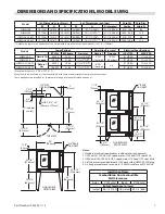
Clearances
Combustible and non-combustible wall clearances are: side,
1.0” (25mm) and rear, 3.0” (76mm).
Location
Each gas appliance shall be located with respect to building
construction and other equipment so as to permit access to
the appliance. Such access and clearance may be necessary
for servicing and cleaning.
IMPORTANT: All gas burners and pilots need sufficient air
to operate and large objects should not be placed in front
of this oven, which would obstruct the airflow through the
front. Objects should not be placed on main top rear of oven
while in use. This could obstruct the venting system of the
unit’s flue products.
Installation Of Ovens
Equipped With Casters
A. For an appliance equipped with casters, the installation
shall be made with a connector that complies withthe
Standard for Connectors for Movable Gas Appliances,
ANSI Z21.69 /CSA 6.16, and a quick-disconnect device
that complies with the Standard for Quick-Disconnect
Devices for Use With Gas Fuel, ANSI Z21.41 / CSA 6.9,
and adequate means must be provided to limit the
movement of the appliance without depending on
the connector and the quick-disconnect device or its
associated piping to limit the appliance movement and
the location(s) where the restraining means may be
attached to the appliance shall be specified.
B. The front casters of the unit are equipped with brakes
to limit the movement of the oven without depending
on the connector and any quick-disconnect device or its
associated piping to limit the appliance movement.
C. The restraint can be attached to the unit near the gas
inlet. If the restraint is disconnected, be sure to reconnect
the restraint after the oven has been returned to its
originally installed position.
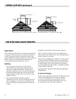
Installation of Double Deck Models
A. Position insert in bottom leg opening and tap insert up
into leg until it seats at collar. Attach six inch (6”, 152mm)
legs to lower oven section. Raise unit or lay on its left side.
Place the front legs on the oven so as to line up with four
(4) attaching bolt holes. Secure leg to oven frame using
(4) 3/8-16 x 3/4 bolts and washers provided. Repeat at
rear of unit.
B. Remove lower front cover of top deck (located under
oven doors). Raise top deck into place and line up body
sides and back of the unit. Fasten the rear of the units
together, with the stacking bracket, using (6) 1/4-20
machine screws, lock washers and nuts, (provided).
C. Install the interconnecting flue parts, carefully following
the instructions contained in the stacking kit. Pay
particular attention to the type of ovens you are stacking
and be sure to follow the corresponding instructions.
Summary of Contents for Manitowoc Summit series
Page 2: ......
Page 4: ...THIS PAGE INTENTIONALLY LEFT BLANK...
Page 6: ...THIS PAGE INTENTIONALLY LEFT BLANK...
Page 22: ...THIS PAGE INTENTIONALLY LEFT BLANK...
Page 23: ......
Page 26: ......
Page 27: ...CETTE PAGE EST LAISS E BLANCHE INTENTIONNELLEMENT...
Page 43: ...CETTE PAGE EST LAISS E BLANCHE INTENTIONNELLEMENT...
Page 45: ...CETTE PAGE EST LAISS E BLANCHE INTENTIONNELLEMENT...
Page 47: ......


