background image

106636-04 - 8/22

27

 X-2

Installation, Operating & Service Manual

11 

Operation 

(continued)

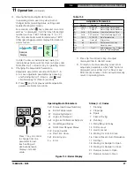
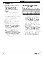
Figure 11-4: Boiler Display

4.

  Viewing the Operating Mode Options.


In operating mode, user may view (but not   


change) boiler operating status, settings and  


troubleshooting information.  


For example, when “

I

I

” key is pressed on control  


until “

bt

” is displayed, it will then flash three digit  


number (such as “180”) followed by “

F

” (or “

C

”).   


This indicates boiler water temperature is 180°F.   


Other operating parameters display information in  


similar fashion.

Unit Display

OR

Sample 

Display

1 sec

1 sec

1 sec


In order to view an instantaneous value, [i.e. 

instantaneous flame current.] User can press and 

hold either Up 

 or Down 

 key in operating mode 

5.  Changing the Adjustable Parameters.
 

Adjustable parameters are listed in Table 11-3.
A.  Access adjustable parameters by pressing 

and holding the Up 

, Down 

, and “

I

I

” keys 

simultaneously for three (3) seconds.  

B. Press

 "

I

I

key to display available adjustable 

parameters. Select an optio

n. 

Operating Mode Parameters

StA

Status (see Status Numbers)

bt

Boiler Temperature

SP

Operating Setpoint 

HL

High Limit Setpoint

HdF

High Limit Differential Setpoint

tt

Heat Request Status

dh

DHW Heat Request Status

FLA

Flame Current

run

Run Time Hours

CYC

Boiler Cycles

Err

Error

Press "I" key on control 

to change from one 

parameter to next. 

Each setting will 

alternate between 

display code and 

value.

Status (

StA

) Codes

1 Standby
4 Prepurge
6 Spark
7 Flame Proving
8 Running

10 Retry/Recycle Delay
13 Soft Lockout
14 Hard Lockout 
15 Waiting for Limit to Close
16 Flame Present Out of Sequence
17 Self Test
18 Waiting for Damper to Open
19 Waiting for Damper to Close
20 Damper Failure to Open
21 Damper Failure to Close


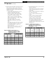
Adjustable Parameters

Default

Range

Description

HL_

180oF

140-220°F

Adjust High Limit Setting

dF_

15oF

10-30°F

Adjust High Limit Differential

Or_

0 min

0-10 minutes Circulator Overrun Time 

PP_

2 min

2-20 minutes Circulator Pre-purge Time 

St_

140oF

140-180°F

Start Temperature

Pt_

on

On or off

Priority time

dh_

dh

dh or tt2

DH Terminal Function

rst

F

Reset Lockout

f-C

F

F or C

Select degrees F or C Mode

bac

Back to Operating Mode

C. Press Up


and Down


keys to adjust 

displayed item to desired value.

D. To return to normal operating screen from 

adjustable parameters, when

 "

bAc

” 

option is 

displayed, press either Up 


or


Down


key.  

After five (5) minutes control will automatically 

return to operating mode. 

Table 11-3

Summary of Contents for X-202

Page 1: ...er Read Before Proceeding 3 2 User Homeowner Read Before Proceeding 4 3 Specifications 5 4 Locating Boiler 6 5 Preparing Boiler 9 6 Venting 9 7 Water Piping 12 8 Gas Piping 16 9 Electrical 17 10 Syste...

Page 2: ...rate injury WARNING Indicates a hazardous situation that if not avoided could result in death or serious injury DANGER Explosion Hazard DO NOT store or use gasoline or other flammable vapors or liquid...

Page 3: ...l and free of pressure and that your clothing will protect you from a release of hot water or steam Do not rely solely on boiler temperature and pressure gauge when making this judgement Install all g...

Page 4: ...er installing CO alarms near bedrooms in all levels of building to warn you and your family of potential CO exposure Do not block air flow into or around boiler or opening for fresh air into boiler ro...

Page 5: ...26 47 1 X 203 254 180 39 26 47 2 X 204 304 231 39 26 47 3 X 205 357 284 39 26 47 4 X 206 405 332 39 26 47 5 X 207 462 382 39 35 47 6 X 208 518 438 39 35 47 7 X 209 564 484 39 35 47 8 Table 3 3 Weights...

Page 6: ...stible materials gasoline or other flammable liquids from area around boiler 8 Check for and remove any potential combustion air contaminants from area around boiler See Table 4 1 Clearances 1 Provide...

Page 7: ...room exhausts so they will operate at maxi mum speed Do not operate a summer exhaust fan Close fireplace dampers Before Removing Existing Boiler Take pictures and measure and or mark existing steam an...

Page 8: ...ontal section of vent connector within reach of vent damper harness Area of each opening to be 1 sq inch for each 1 000 BTU hr 1 MBH input with minimum of 100 sq inches Height of opening should be hal...

Page 9: ...uctions in Section 4 Locating Boiler when removing a boiler from an existing vent system Maintain clearances to vent piping and draft hood per Figures 4 1 and 4 2 Do not use CPVC PVC Polypropylene or...

Page 10: ...alled 6 Venting continued Figure 6 1 Vent Damper Installation Figure 6 2 Vent Damper Position Indicator A Vent damper must be same size as outlet of vent supplied with boiler see Table 3 2 Unpack damp...

Page 11: ...terminal not less than 1 4 in per foot F Support horizontal portions of venting system to prevent sagging Use pipe straps brackets or hangers spaced 4 ft or less G Vent pipe must be inserted into but...

Page 12: ...m leaks repairing fittings and using non permeable materials in distribution system 2 Install circulator with flanges gaskets and bolts provided 3 Install Safety Relief Valve See Figure 7 1 Safety Rel...

Page 13: ...a boiler bypass if boiler is to be operated in a system which has a large volume or excessive radiation where low boiler water temperatures may be encountered i e converted gravity circulation system...

Page 14: ...tem Zone Valves Zone Circulators Full Port Isolation Valves Flow Check From System Full Port Isolation Valves Drain Valve Safety Relief Valve Pipe within 6 of floor or drain Drain Valve IWH Return IWH...

Page 15: ...Drain Valve IWH Return IWH Supply Indirect Water Heater IWH Air Separator Air Vent Expansion Tank Backflow Preventer Fill Valve Cold Water Return Full Port Isolation Valves Unions Flow Check IWH Circu...

Page 16: ...petroleum gas C Install sediment trap ground joint union and manual shut off valve upstream of boiler gas control valve See Figure 8 2 within 6 ft of boiler D All above ground gas piping upstream fro...

Page 17: ...ee Figures 9 1 and 9 2 4 For installations using zone valves provide separate transformer for zone valve wiring Consult zone valve manufacturer for assistance See Figure 9 3 9 Electrical WARNING Elect...

Page 18: ...106636 04 8 22 18 X 2 Installation Operating Service Manual Figure 9 1 Wiring Connection Diagram 9 Electrical continued...

Page 19: ...106636 04 8 22 19 X 2 Installation Operating Service Manual Figure 9 2 Schematic Ladder Diagram 9 Electrical continued...

Page 20: ...106636 04 8 22 20 X 2 Installation Operating Service Manual 9 Electrical continued Figure 9 3 Wiring Schematic Zone Valves Figure 9 4 Wiring Schematic Zone Circulators...

Page 21: ...essure reducing valve system will automatically fill to 12 psi K Remove hose from drain valve DANGER Explosion Hazard Do not use matches candles open flames or other ignition sources to check for leak...

Page 22: ...106636 04 8 22 22 X 2 Installation Operating Service Manual Figure 10 1 Operating Instructions 10 System Start up and Checkout continued...

Page 23: ...Figure 10 3 Natural Gas Pilot Flame Figure 10 4 LP Gas Pilot Flame Figure 10 2 Top View of Gas Valve LP Gas Only Pilot burner produces three 3 flames The center flame should be steady medium hard blu...

Page 24: ...ge that blows out manometer fluid B Adjust regulator on gas valve so manifold pressure matches values listed on rating label C Turning regulator adjustment screw clockwise increases pressure D Turning...

Page 25: ...er should shut down Set thermostat to call for heat and push TEST button on IDL 1200 to simulate low water condition Amber LOW WATER LED will illuminate and burner will shut down Release TEST button a...

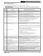
Page 26: ...o light off again Limit Open 15 There is a call for heat from thermostat but Limit is open Flame Present Out of Sequence 16 Flame signal is still present when expected to be 0 no flame Damper Failed t...

Page 27: ...F High Limit Differential Setpoint tt Heat Request Status dh DHW Heat Request Status FLA Flame Current run Run Time Hours CYC Boiler Cycles Err Error Press I key on control to change from one paramete...

Page 28: ...oiler water temperature is less than 140 F This feature helps save energy by satisfying home heating needs with residual boiler heat rather than cycling boiler E Start Temperature Amount of heat avail...

Page 29: ...ter Demand dh IWH limit is wired to DHW terminal on control DHW circulator is wired to DHW Circulator on control wire harness Table 11 6 shows circulator status with different combinations of TT Input...

Page 30: ...ressure Checked gas manifold pressure Checked CO level in vent Checked vent damper operation Check ignition system safety shut off device Tested LWCO functionality Tested high limit operation Tested a...

Page 31: ...ing that is sufficiently tight around potential entry points for RCF dust 3 Gloves 4 Eye protection such as goggles safety glasses with side shields or full facepiece Take steps to assure adequate ven...

Page 32: ...ns in vent pipe and chimney B If masonry chimney is lined verify lining is in good condition and there are no openings into chimney C Remove soot accumulations with wire brush and vacuum D Repair or r...

Page 33: ...e and ground wire at Boiler Control F Install Burner Access Panel Connect Flame Rollout Switch wires 5 Inspect Water Piping A Check all system piping for leaks B Repair any leaks before placing back i...

Page 34: ...Provides adequate dilution air and ensures proper draft for boiler operation Blocked Vent Switch If vent becomes blocked switch will open requiring manual reset and cause burners to shut down 4 Flame...

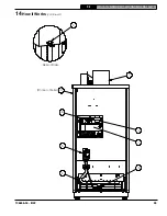
Page 35: ...106636 04 8 22 35 X 2 Installation Operating Service Manual 3 5 4 6 7 On rear of boiler 8 2 1 Rear of Boiler 3 A B 14 How It Works continued...

Page 36: ...rious and potentially dangerous condition In the event the IDL 1200 detects a low water condition the system must be inspected by a qualified service technician before the boiler is returned to servic...

Page 37: ...If 24 VAC is present unplug vent damper harness from control With wire harness unplugged check for 24 VAC between P6 5 on Control and ground If voltage present replace control If voltage not present...

Page 38: ...draft Always follow recommended clearances combustion air requirements and venting requirements Check Flame Rollout Switch in event of excessive blockage of boiler section flue passageways is develop...

Page 39: ...recommended corrective action Flame sensed during pre purge before gas valve signaled open Check gas valve for proper operation Replace gas valve if problem persists Hard Lockout When a hard lockout...

Page 40: ...upply tubes of air b If no gas flow check following 24 volts across PV and MV PV at gas valve If voltage ok replace defective gas valve Check for break in wiring harness to gas valve 24 volts across c...

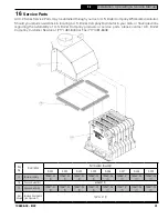
Page 41: ...617 03 1 109617 04 1 109617 05 1 109617 06 1 109617 07 1 109617 08 1 109617 09 1 Not Shown Blocked Vent Switch see Figure 6 1 109742 01 1 All X 2 Series Service Parts may be obtained through your loca...

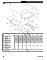
Page 42: ...09613 08 1 Nat Gas 109613 09 1 2B Base Tray 2C Burner Tray 2D Base Side Insulation 2E Base Rear Insulation 2F Base Front Insulation 2G Drip Shields 2H Manifold Support Bracket LP Gas 110097 03 1 LP Ga...

Page 43: ...A in Gas Manifold N A 109731 07 1 109731 08 1 109731 09 1 3C Burner Orifices Natural Gas 46 109732 01 1 47 109733 01 1 16 orifices Burner Orifices LP Gas 1 25 mm 109735 01 1 1 20 mm 109734 01 1 16 ori...

Page 44: ...y No Description Part Number Quantity X 202 X 203 X 204 X 205 X 206 X 207 X 208 X 209 4A Control 103966 02 1 4B Transformer 106034 01 1 4C Temperature Sensor LWCO 106495 02 1 Not Shown Temperature Sen...

Page 45: ...cket Wrap around Jacket Panel 106357 03 1 106357 04 1 106357 05 1 106357 06 1 106357 07 1 106357 08 1 106357 09 1 5B Jacket Vestibule Panel 110126 02 1 110126 03 1 110126 04 1 110126 05 1 110126 06 1...

Page 46: ...9 6A Supply Water Manifold 109614 01 1 6B Temperature Pressure Gauge 105894 01 1 6C 30 PSI Relief Valve 109038 01 1 6D Drain Valve Obtain Locally 3 4 in NPT boiler connection 6E Vent Damper 109634 01...

Page 47: ...ity X 202 X 203 X 204 X 205 X 206 X 207 X 208 X 209 7A Power Supply Harness 109639 01 1 7B Main Control Harness 109640 01 1 7A 7B Key No Description Part Number Quantity X 202 X 203 X 204 X 205 X 206...

Page 48: ...e Appendix A Combination Refrigeration Heating System Water Chiller Shut off valves Shut off valves Expansion Tank Circulator Supply main to combined heating cooling system Return main from combined h...

Page 49: ...valvemayopenfrequently resultinginregular additions of make up water D If an automatic fill valve is installed installation of a water meter in fill line is strongly recommended so routine additions o...

Page 50: ...condensing during these heating season shoulders is unlikely to cause problems Larger volume systems during the shoulder heating seasons or systems with aggressive set back or low temperature systems...

Page 51: ...s A strap on temperature sensor measures boiler inlet temperatures This temperature signal is sent to a variable speed pump that will ensure boiler inlet temperatures are always greater than the facto...

Page 52: ...106636 04 8 22 52 X 2 Installation Operating Service Manual U S Boiler Company LLC P O Box 3020 Lancaster PA 17604 1 888 432 8887 www usboiler net...

Reviews: