background image

QUICK START GUIDE

15

USER GUIDE

u-line.com

General Installation

Connections

When complete, the connections should look like this:

LEVELING INFORMATION

1. Use a level to confirm th

unit is level. Level should
be placed  along top edge
and side edge as shown.

2. If the unit is not level,

shim as needed.

3. Confirm the unit is l vel

after each adjustment
and repeat the previous
steps until the unit is
level.

Keg

Keg

Infuser 

Regulators

Filter 

Assembly

Filter 

Assembly

To comply with applicable federal, state, 
and local codes, it may be necessary to 
caulk the refrigerator to the floo .

CASTERS (optional)

1. Remove grille and back panel to access nuts.

2. Remove each nut and unscrew each leg.

3. Install each caster and secure with nut.

Tighten with included wrench.

4. Replace grille and back panel.

When ready to use, see FIRST USE section in 
this manual.

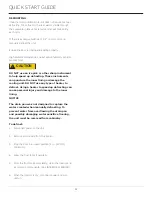
CAUTION

!

Summary of Contents for CDE224B

Page 1: ...QUICK START GUIDE DISPENSERS CDE224B 115v 3 Tap Coffe 30660_E...

Page 2: ...re available worldwide U Line RIGHT PRODUCT RIGHT PLACE RIGHT TEMPERATURE PRODUCT INFORMATION Looking for additional information on your product User Guides Spec Sheets CAD Drawings Compliance Documen...

Page 3: ...r product For more details see the complete User Guide Service Manual on u line com CONTENTS Safety and Warning 4 Environmental Requirements 5 Electrical 5 Door Swing 5 Door Adjustments 6 General Inst...

Page 4: ...safe for regular use Do not use sharp objects to expedite defrosting Do not service without consulting the R600a specifications section included in th User Guide Do not damage the refrigerant circuit...

Page 5: ...nnect power to the unit Always keep your working area dry NOTICE Electrical installation must observe all state and local codes This unit requires connection to a grounded three prong polarized recept...

Page 6: ...st the door 1 Gently pry off hinge c ver from top of unit 2 Loosen do not remove top and bottom hinge screws using a Philips screwdriver on the top and a 1 4 socket on the bottom 3 Align door squarely...

Page 7: ...a 1 4 socket 2 Remove corresponding screws on opposite side of cabinet On some models there may be a nut behind one or both screws on either side Install bottom hinge Install two or three screws depen...

Page 8: ...7 Four casters 2 locking 2 non locking Safety and Warning Keep nitrogen tank in an upright position and handle with care Never exceed 60 PSI Ventilate area after nitrogen leak Required not included 1...

Page 9: ...ses to Tower Make all the hose connections to the tower prior to installing tower onto refrigerator 1 Attach gas jumper hoses line up and press in firml Note The connectors at the ends of the gas jump...

Page 10: ...nd connect to main source 6 Remove top cap from refrigerator and carefully slide refrigerator under countertop 7 Connect nitrogen and liquid lines to tower and feed lines through hole all the way into...

Page 11: ...LE DO THE FOLLOWING 1 Measure the inch scale 2 Line up the gasket to the template 3 If this template cannot be verified DO N T USE Use measurements and gasket only WARNING TO PREVENT IRREPARABLE DAMAG...

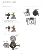
Page 12: ...off position turned clockwise as far as it ca go 2 Attach regulators to nitrogen tank Hand tighten the coupling nut and then use an adjustable wrench for an additional quarter turn DO NOT OVER TIGHTE...

Page 13: ...pler down firml onto in valve Release collar listen for a click Pull up on the coupler to ensure it is locked down 3 Attach infuser hoses to T connectors on infuser regulators In Valve 1 Attach black...

Page 14: ...nt to the inside of the gasket 3 In the back of the unit remove back panel 4 Insert gasket ring into hole that corresponds to the drilled out hole in bulkhead and apply food grade lubricant to inside...

Page 15: ...el after each adjustment and repeat the previous steps until the unit is level Keg Keg Infuser Regulators Filter Assembly Filter Assembly To comply with applicable federal state and local codes it may...

Page 16: ...etc U Line recommends allowing the unit to reach set points before loading To dispense cold coffe make sure the components are assembled according to the instructions in GENERAL INSTALLATION NOTICE DE...

Page 17: ...te the red regulator valve to ON Position turn counterclockwise 1 4 turn until it stops 4 To adjust pressure loosen locking nut turn adjusting screw until desired pressure is reached and retighten loc...

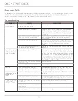
Page 18: ...he secondary regulator is set to a pressure that is either too high or low If there is less more nitro effect than desi ed use the black knob on the secondary regulator assembly to make a change To ad...

Page 19: ...not use stainless steel cleaners or polishes on any glass surfaces Clean any glass surfaces with a non chlorine glass cleaner Do not use cleaners not specifically intended for stainless steel on stain...

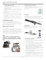
Page 20: ...se 2 Pour the cleaning solution into keg attach hoses and open the nitrogen valve to pressurize the system 3 Place a bucket under the taps Pull and hold the left tap open until approximately gallon of...

Page 21: ...cture the inner lining or damage the cooling unit DO NOT use any type of heater to defrost Using a heater to speed up defrosting can cause personal injury and damage to the inner lining NOTICE The dra...

Page 22: ...improper use maintenance installation service repair acts of God fire flood or other natural disasters The product must be installed operated and maintained in accordance with your product s User Guid...

Reviews: