LEON-G100 / LEON-G200 - System Integration Manual
GSM.G1-HW-09002-G3
Preliminary
System description
Page 40 of 125
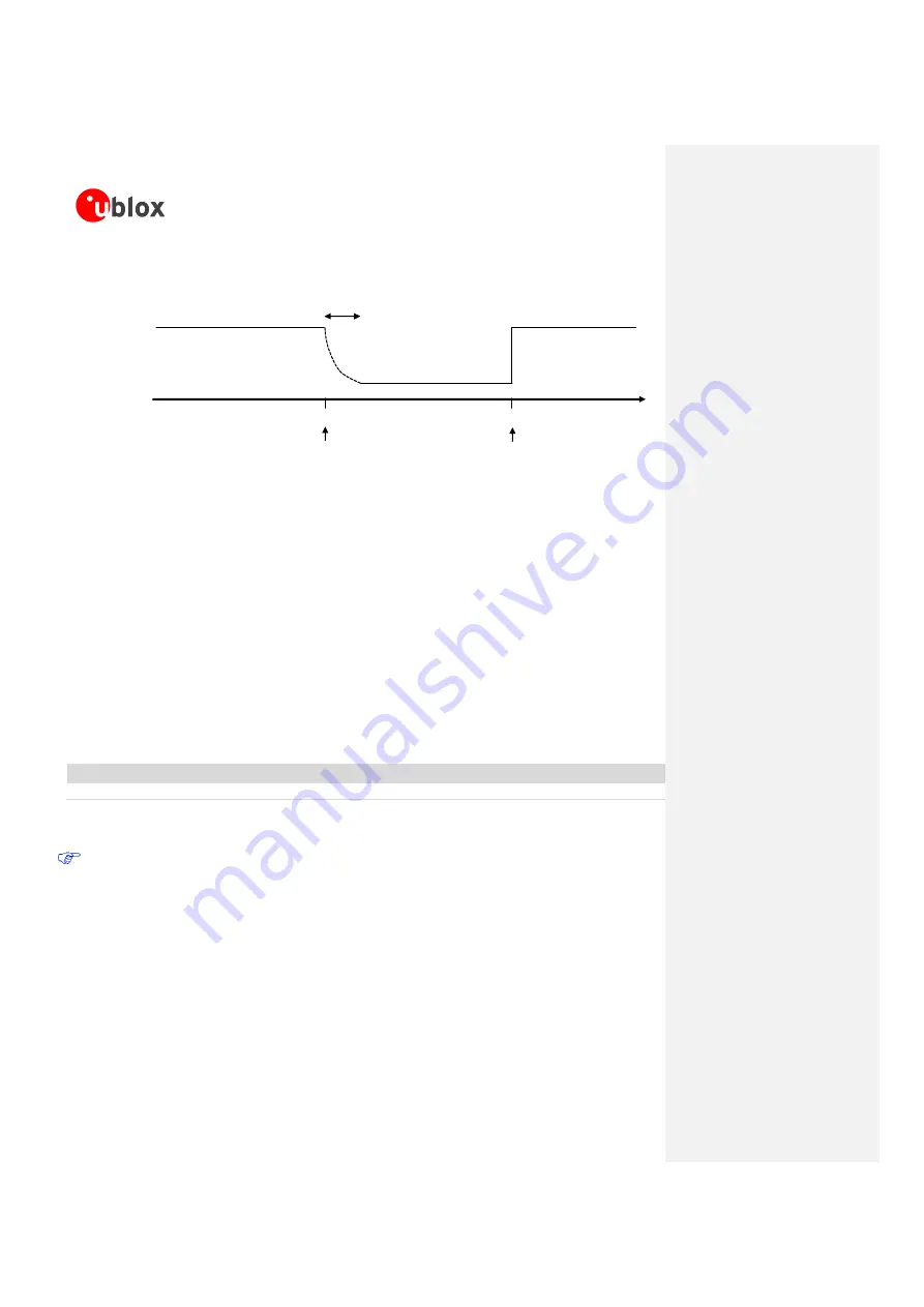
Depends on the
pull-down strength
(~35 µs with 680 k)
time [µs]
160
0
LOW = 0 V
HIGH = 1.88 V
Reset state start
Reset state end
RESET_N
Figure 23: RESET_N behavior due to an internal reset
1.6.4
Note: Tri-stated external signal
Any external signal connected to the UART interface, I
2
S interfaces and GPIOs must be tri-stated when the
module is in power-down mode, when the external reset is forced low, and during the module power-on
sequence (at least for 3 s after the start-up event), to avoid latch-up of circuits and allow a proper boot of the
module. If the external signals connected to the wireless module cannot be tri-stated, insert a multi channel
digital switch (e.g. Texas Instruments SN74CB3Q16244, TS5A3159, or TS5A63157) between the two-circuit
connections and set to high impedance during module power down mode, when external reset is forced low
and during power-on sequence.
1.7
RF connection
The
ANT
pin has 50
Ω
nominal impedance and must be connected to the antenna through a 50
Ω
transmission
line to allow transmission and reception of radio frequency (RF) signals in the GSM operating bands.
Name
Description
Remarks
ANT
RF antenna
50
nominal impedance.
Table 13: Antenna pin
ANT
port ESD immunity rating is 4 kV (according to IEC 61000-4-2). A higher protection level could be
required if the line is externally accessible on the application board. A higher protection level can be
achieved with an external high pass filter, consists of a 15 pF capacitor (e.g. the Murata
GRM1555C1H150JA01) and a 39 nH coil (e.g. Murata LQG15HN39NJ02) connected to the
ANT
port.
The antenna detection functionality will be not provided implementing this high pass filter for ESD
protection on the ANT port.
Choose an antenna with optimal radiating characteristics for the best electrical performance and overall module
functionality. An internal antenna, integrated on the application board, or an external antenna, connected to the
application board through a proper 50
Ω
connector, can be used. See section 2.4 and 2.2.1.1 for further details
regarding antenna guidelines.


