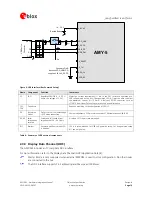

AMY-5M
-
Hardware
Integration
Manual
Objective
Specification
Design-In
GPS.G5-MS5-08207
u-blox
proprietary
Page 26
your position is our focus
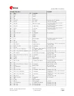
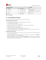
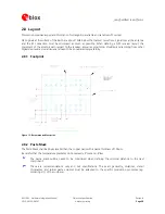
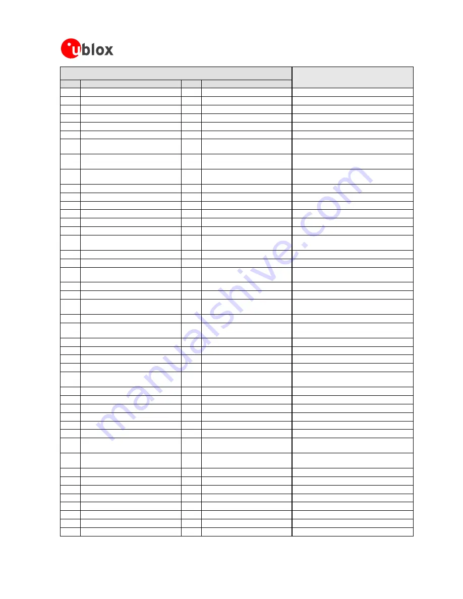
Standard Function
Remarks
No
Name
I/O
Description
A1
RF_IN
I
RF
Input
A2
GND
I
Ground
A3
NC
A4
GND
I
Ground
A5
XTAL_OUT
O
RTC
Output
Leave
open
if
no
RTC
attached.
A6
XTAL_IN
I
RTC
Input
GND
if
no
RTC
attached.
A7
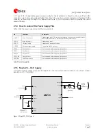
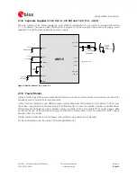
VDD_LNA
O
LNA
Power
Supply
See
how
to
connect
power
in
Section
2.1
(Power
Management).
A8
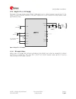
VDD_ANA
O
Analog
Power
See
how
to
connect
power
in
Section
2.1
(Power
Management).
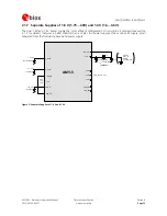
A9
VDD_RF
I
Core
Power
See
how
to
connect
power
in
Section
2.1
(Power
Management).
B1
GND
I
Ground
B2
GND
I
Ground
B3
PIO14
/
CFG_CLK1
I/O
Configuration
Do
not
connect
B4
GND
I
Ground
B5
GND
I
Ground
B6
GND
I
Ground
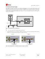
B7
V_TH
I
Reset
Threshold
See
how
to
connect
power
in
Section
2.1
(Power
Management).
B8
GND
I
Ground
B9
VDD_USB
I
USB
Power
C1
PIO8
/
EXTINT1
I
External
Interrupt
Pull-up
resistor
to
VDDIO.
If
not
used
connect
to
VDDB
or
GND.
C2
PIO13/
CFG_CLK0
I/O
Configuration
Do
not
connect
C7
USB_DM
I/O
USB
Leave
open
if
not
used.
C8
PIO18
/
CFG_FFU3
/
TIMEPULSE
I/O
Configuration.
Do
not
connect
if
not
used
for
TIMEPULSE.
Leave
open
if
not
used.
C9
PIO21
/
CFG_GPS0
/
SCK
/
GPSMON2
I/O
Configuration
Leave
open
if
not
used.
D1
PIO7
/
EXTINT0
I
External
Interrupt
/
Time
Mark
Pull-up
resistor
to
VDDIO.
If
not
used
connect
to
VDDB
or
GND.
D2
PIO22
/
CFG_GPS1
/
CS1_N
/
SCS1_N
I/O
Configuration
Leave
open
if
not
used.
D7
USB_DP
I/O
USB
Leave
open
if
not
used.
D8
V_RESET
I
Supply
Monitor
Connect
to
VDD_3V.
D9
VDD_3V
I
Main
RF
Supply
E1
TMS
/
CFG_PIN
I
SF
Register:
BOOTMODE1
Set
to
GND
if
external
memory
attached,
otherwise
leave
open.
E2
TCK
I
Leave
open
if
not
used.
E8
PIO23
/
CFG_GPS2
/
CS3_N
/
SCS2_N
I/O
Configuration
Connect
always
to
GND.
E9
VDD_B
O
Backup
Power
NC
or
supply
cap
F1
TDO
/
TIMEPULSE
I/O
Leave
open
if
not
used.
F2
GND
I
Ground
F3
PIO17
/
CFG_FFU2
I/O
Configuration.
Do
not
connect.
Leave
open
if
not
used.
F4
PIO19
/
CFG_COM0
/
MOSI
I/O
Configuration
Leave
open
if
not
used
for
communication
or
configuration.
F5
PIO20
/
CFG_COM1
/
MISO
I/O
Configuration
Leave
open
if
not
used
for
communication
or
configuration.
F6
PIO6
/
SS_N
I/O
SPI
Leave
open
if
not
used.
F7
PIO15/
CFG_CLK2
I/O
Configuration
Do
not
connect
F8
GND
I
Ground
F9
V_DCDC
I
Main
Core
Supply
G1
VDD_IO
I
I/O
Ring
Supply
1.65-3.6V
G2
TDI
/
SAFEBOOT_N
I
SF
Register:
BOOTMODE0
Leave
open
if
not
used.
G3
PIO3
/
SCL2
I/O
DDC
for
peripherals
Leave
open
if
not
used.
G4
PIO2
/
SDA2
I/O
DDC
for
peripherals
Leave
open
if
not
used.


