


35
Note : The asterisk “*” indicates that this component is specially designed for use on double-action
clutch.
C. When the first of clutch pedal is depressed, the three release levers actuate the clutch pressure plate
through adjusting bolts to disengage the master clutch, interrupting power transmission to the running
system on the tractor, while the clearance (1
±
0.1) at the three pull-rods is eliminated and the clutch for
power take-off continues to work. Only the clutch pedal is further depressed, can the full-rod drive the
pressure plate of PTO clutch to disengage the PTO clutch. The second stage of disengagement cuts off
power transmission to power take-off shaft. As the clutch pedal is released, the PTO clutch is first
engaged and then the master clutch. The user can be trained to accurately distinguish the stage of
release. For apprentice drivers who are not skillful enough to operate the clutch and only want to
release the first working stage, a limiting mechanism on the clutch release lever can be used to control
the first stage working travel.
(3) Repair and Maintenance
A. The clutch should engage smoothly and disengage thoroughly. If any problem is found, check and
adjust relevant clearance if necessary.
B. During technical maintenance Class 111, oil in the rear of bridge casing (the same as used in the
transmission) should be changed. The oil level should be at the lower edge of the screw hole to ensure
that the oil thrower weldment can provide lubrication for bearing.
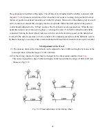
5.3 Adjustment of Transmission
A. The spring scale reading after preloading the
front bearing of the second shaft
B. The spring scale reading after preloading the
differential bearing and that of the front bearing
of the second shaft.
1. Circular nut
2. Front bearing cover of the second shaft
3. Transmission housing 4. Special wrench
5. Spring scale
Fig. 5-2 Preloading of front bearing of the second
shaft and that of the differential bearing
Summary of Contents for ET350 ECONO
Page 69: ...62 8 3 Electrical system wiring diagram...
Page 73: ...66 ET 350 ECONO 4WD TRACTOR ENGINE PARTS CATALOGUE...
Page 74: ...67 1 INTAKE AND EXHAUST PIPE ASSEMBLY...
Page 76: ...69 2 CYLINDER HEAD ASSEMBLY...
Page 80: ...73 3 CYLINDER BLOCK ASSEMBLY...
Page 84: ...77 4 CAMSHAFT ASSEMBLY...
Page 86: ...79 5 CRANKSHAFT FLYWHEELASSEMBLY...
Page 88: ...81 6 PISTON CONNECTING ROD ASSEMBLY...
Page 90: ...83 7 FUEL SYSTEM ASSEMBLY...
Page 92: ...85 8 COOLING SYSTEM...
Page 95: ...88 9 LUBRICATION SYSTEM ASSY...
Page 97: ...90...
Page 98: ...91 Electric EGR Illustration Diagram...
Page 100: ...93 ET 350 ECONO 4WD TRACTOR Chassis PARTS CATALOGUE...
Page 102: ...95 1 DRY AIR FILTER...
Page 104: ...97 2 ENGINE CONTROL MECHANISM ASSY...
Page 107: ...100 3 CLUTCH...
Page 110: ...103 4 INTERMEDIATE HOSE ASSY...
Page 113: ...106 5 TRANSMISSION HOUSING...
Page 116: ...6 PRIMARY SHAFT 109...
Page 118: ...7 MAIN SHAFT 111...
Page 120: ...8 TRANSMISSION COVER ASSY 113...
Page 122: ...9 DIFFERENTIAL 115...
Page 124: ...10 PTO SHAFT ASSY 117...
Page 126: ...11 BRAKE ASSY 119...
Page 129: ...122 12 REAR DRIVING WHEEL ASSY...
Page 131: ...124 13 FINAL DRIVE ASSY...
Page 134: ...14 FUEL TANK BRACKET 127...
Page 136: ...15 SUSPENSION LINKAGE ASSY 129...
Page 139: ...16 FRONT DRIVING AXLE ASSY A 132...
Page 142: ...17 FRONT DRIVING AXLE ASSY B 135...
Page 145: ...138 18 FRONT DRIVING AXLE ASSY C...
Page 147: ...140 19 FRONT DRIVING AXLE ASSY D...
Page 150: ...143 20 FRONT DRIVING WHEELASSY...
Page 152: ...145 21 STEERING MECHANISM...
Page 154: ...147 22 TRANSFER CASE ASSY...
Page 157: ...150 23 HYDRAULIC POWER LIFT...
Page 160: ...153 24 POWER LIFT CONTROL MECHANISM...
Page 163: ...156 25 CYLINDER DISTRIBUTOR ASSY...
Page 166: ...159 26 FENDER FLOOR BOARD TOOL BOX...
Page 168: ...161 27 BONNET 1...
Page 171: ...164 28 BONNET 2...
Page 173: ...166 29 SIDE COVER...
Page 175: ...ET350 ECONO OPERATOR S MANUAL FOR TRACTORS CODE NO Printed on June 2006 2 nd EDITION...


