


27
Opening pressure (MPa) of
system release valve : 14
±
0.5
cylinder release valve : 18
±
0.5
Rated lifting capacity(N) : 7850(at lower draw-bar hitch point)
Dim. and Qty. of oil outlets : M18X1.5;1
(2) To operate the hydraulic lift
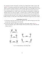
When a tractor operates in the field, the control of working depth is selected according to its
attachments and job requirements. There are three ways available for working depth control through
putting the control handle at different positions on the sector plate, which include position control,
draft and position combined control and float control. The upper segment on the sector plate is for
position control, the middle for combined control and the lower for draft control.
There are a hydraulic output connection and a control valve for lowering speed, located on the
cylinder head in the front end of hydraulic lift. The lowering speed control valve also hand wheel
clockwise will slow down the lowering speed. As the hand wheel is turned to the end, the pressure oil
in the cylinder will completely sealed to lock the hydraulic system. Hydraulic locking is necessary
when a tractor attached with implement travels from one spot to another. When the hydraulic output is
used, the lifting arm must be at its lowest position and the hydraulic system must be completely locked
to enclose oil from entering into the cylinder. To supply hydraulic output, operate the handle.
4.4 Operation of Electrical Equipment
The electrical equipment of the tractor is used to start engine, meet the needs of giving indication signals
and lighting for operation at night, etc.. Therefore it is very important to use the electrical equipment
correctly.
1. Battery
A. Preparation
(1) Clean the surface of a new battery. Screw off the plastic cover and make the air hole on the cover
open.
(2) The specific gravity of the electrolyte used in the battery is 1.26(15
°
C) in the tropics, 1.28(15
°
C) in
temperate zone and 1.29(15
°
C) in frigid zone. Fill the battery with the electrolyte when it cooled to
25~30
°
C. After a standstill of 20 minutes, the battery can be used.
(3) The electrolyte level should be 10~15mm above the protecting plate.
(4) If the battery is stored over a year, it should be changed with electric current of 11.5A for 5 hours.
Summary of Contents for ET350 ECONO
Page 69: ...62 8 3 Electrical system wiring diagram...
Page 73: ...66 ET 350 ECONO 4WD TRACTOR ENGINE PARTS CATALOGUE...
Page 74: ...67 1 INTAKE AND EXHAUST PIPE ASSEMBLY...
Page 76: ...69 2 CYLINDER HEAD ASSEMBLY...
Page 80: ...73 3 CYLINDER BLOCK ASSEMBLY...
Page 84: ...77 4 CAMSHAFT ASSEMBLY...
Page 86: ...79 5 CRANKSHAFT FLYWHEELASSEMBLY...
Page 88: ...81 6 PISTON CONNECTING ROD ASSEMBLY...
Page 90: ...83 7 FUEL SYSTEM ASSEMBLY...
Page 92: ...85 8 COOLING SYSTEM...
Page 95: ...88 9 LUBRICATION SYSTEM ASSY...
Page 97: ...90...
Page 98: ...91 Electric EGR Illustration Diagram...
Page 100: ...93 ET 350 ECONO 4WD TRACTOR Chassis PARTS CATALOGUE...
Page 102: ...95 1 DRY AIR FILTER...
Page 104: ...97 2 ENGINE CONTROL MECHANISM ASSY...
Page 107: ...100 3 CLUTCH...
Page 110: ...103 4 INTERMEDIATE HOSE ASSY...
Page 113: ...106 5 TRANSMISSION HOUSING...
Page 116: ...6 PRIMARY SHAFT 109...
Page 118: ...7 MAIN SHAFT 111...
Page 120: ...8 TRANSMISSION COVER ASSY 113...
Page 122: ...9 DIFFERENTIAL 115...
Page 124: ...10 PTO SHAFT ASSY 117...
Page 126: ...11 BRAKE ASSY 119...
Page 129: ...122 12 REAR DRIVING WHEEL ASSY...
Page 131: ...124 13 FINAL DRIVE ASSY...
Page 134: ...14 FUEL TANK BRACKET 127...
Page 136: ...15 SUSPENSION LINKAGE ASSY 129...
Page 139: ...16 FRONT DRIVING AXLE ASSY A 132...
Page 142: ...17 FRONT DRIVING AXLE ASSY B 135...
Page 145: ...138 18 FRONT DRIVING AXLE ASSY C...
Page 147: ...140 19 FRONT DRIVING AXLE ASSY D...
Page 150: ...143 20 FRONT DRIVING WHEELASSY...
Page 152: ...145 21 STEERING MECHANISM...
Page 154: ...147 22 TRANSFER CASE ASSY...
Page 157: ...150 23 HYDRAULIC POWER LIFT...
Page 160: ...153 24 POWER LIFT CONTROL MECHANISM...
Page 163: ...156 25 CYLINDER DISTRIBUTOR ASSY...
Page 166: ...159 26 FENDER FLOOR BOARD TOOL BOX...
Page 168: ...161 27 BONNET 1...
Page 171: ...164 28 BONNET 2...
Page 173: ...166 29 SIDE COVER...
Page 175: ...ET350 ECONO OPERATOR S MANUAL FOR TRACTORS CODE NO Printed on June 2006 2 nd EDITION...


