background image

3


STEP 3:  

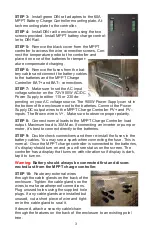
Install green DIN rail adapters to the 60A 

MPPT Battery Charge Controller mounting plate. At-

tach mounting plate to the controller.


STEP 4:  

Install DIN rail to enclosure using the two 

screws provided. Install MPPT battery charge control-

ler to DIN Rail. 


STEP 5:  

Remove the black cover from the MPPT 

controller to access the wire connection screws. Con-

nect the temperature probe to the controller and 

place it on one of the batteries for temper-

ature compensated charging. 


STEP 6:

  Remove the fuses from the bat-

tery cables and connect the battery cables 

to the batteries and the MPPT Charge 

Controller BAT+ and BAT–


connections.


STEP 7:  

Make sure to set the AC input 

voltage selector on the 72V 900W AC/DC 

Power Supply to either 115 or 230 de-

pending on your AC voltage source. The 900W Power Supply can sit in 

the bottom of the enclosure next to the batteries. Connect the Power 

Supply DC output wires to the MPPT Charge Controller PV+ and PV–


inputs. The Brown wire is V+.  Make sure to observe proper polarity.


STEP 8:

  Connect normal loads to the MPPT Charge Controller load 

output. Maximum load is 30A Max. If connecting an inverter or pump or 

motor, it

s best to connect directly to the batteries.


STEP 9:

  Double check connections and then re

-

install the fuses in the 

battery cables. You may see a spark when connecting the fuse. This is 

normal.  Once the MPPT charge controller is connected to the batteries, 

it

s display should turn on and you will see status on the screen. The 

controller has a display that turns on with vibration so if display is dark, 

tap it to turn on.


Warning: 

Battery should always be connected first and discon-

nected last from the MPPT charge controller.


STEP 10:  

Route any external wires 

through the cable glands on the back of the 

enclosure. Tighten the cable glands on the 

wires to make weatherproof connections. 

Plug unused holes using the supplied hole 

plugs. If any cable glands are installed but 

unused, cut a short piece of wire and tight-

en in the cable gland to seal it.


If desired, attach a security cable/chain 

through the features on the back of the enclosure to an existing pole/

tree.


Summary of Contents for UPSPro UPAL24/48-900

Page 1: ...ength Weatherproof Key Lock 24VDC or 48VDC Output 60A MPPT Battery Charge Controller 72V 900W AC DC Power Supply up to 1440Ah Battery Capacity Safety For your own protection follow these safety rules Perform as many functions as possible on the ground Do not attempt to install on a rainy windy or snowy day or if there is ice or snow accumulation at the install site or if the site is wet Make sure ...

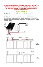
Page 2: ...ntroller ground screw to chassis ground Qwik Install STEP 1 Prepare a foundation to provide level support for the enclo sure STEP 2 Place enclosure on the foundation Install 4 or 8 batteries in the box Batteries are heavy Be sure to have a helper Connect all batteries in series configuration for either 24VDC or 48VDC See Wiring Diagram Below ...

Page 3: ...e Brown wire is V Make sure to observe proper polarity STEP 8 Connect normal loads to the MPPT Charge Controller load output Maximum load is 30A Max If connecting an inverter or pump or motor it s best to connect directly to the batteries STEP 9 Double check connections and then re install the fuses in the battery cables You may see a spark when connecting the fuse This is normal Once the MPPT cha...

Page 4: ...onnect this fan directly to the batteries Note Please see the MPPT solar controller user guide for addition al details TECH CORNER Additional Information you may find useful Solar Ready The system is solar ready You may need to add a 100V 30A blocking diode Tycon pn 5600059 between the solar pan el and the PV input to avoid reverse current from the 72V AC DC power supply going back into the solar ...

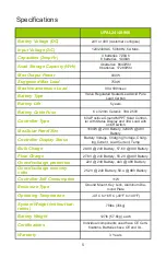
Page 5: ...d with on off switch MaxSolar Panel Size 1600W 24V Battery 3200W 48V Battery Controller Display Status Battery Voltage Charging Voltage Charg ing Current Load Current Temp Bulk Charge 28 8V 24V Battery 57 6V 48V Battery Float Charge 27 6V 24V Battery 55 2V 48V Battery Over discharge protection 22V 24V Battery 44V 48V Battery Over discharge recovery volts 25 2V 24V Battery 50 4 48V Battery Controll...

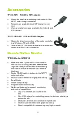
Page 6: ...nitor WEB3 V2 Interfaces with Tycon MPPT solar control lers via RS485 using TPDIN Cable RS485 Logs data and provides remote monitoring and control over the network via Ethernet Interface Single RS485 cable interface to the MPPT solar controller Intuitive user interface and graphical setup Email Alerts SNMP compatibility Programmable functionality Additional features to expand monitoring and contro...

Page 7: ... replacement due to improper installation misuse poor site conditions faulty power etc Lightning or weather damage Physical damage to the external internal parts Products that have been opened altered or defaced Water damage Usage other than in accordance with instructions and the normal intended use Tycon Systems Inc 14641 S 800 W Suite A Bluffdale UT 84065 support tyconsystems com PH 801 432 000...

Page 8: ...8 ...

Reviews: