


http://www.tyan.com
95
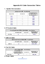
Appendix III: Cable Connection Tables
1. System Fan Connector
System Fan to BP for all Series
System Fan
Connect to
M1302G68-BP12-4
M1303G68A-BP12E-12
M1299G68A-BPE-12
Fan1
→
FAN1
Fan2
→
FAN2
Fan3
→
FAN3
Fan4
→
FAN4
Fan5
→
FAN5
Fan6
→
FAN6
2. FP Control Cable
Front Panel Board (FPB) to S8036 (MB) for all Series
M1724G68-FPB Connect
to
S8036GM2NE-LE
S8036GM2NE
FP CTRL
J1
→
FPIO_2
3. USB 3.0 Cable
USB Panel Board to S8036 (MB) for all Series
M1725G68-USB Connect
to
S8036GM2NE-LE
S8036GM2NE
USB 3.0
J2
→
USB3_FPIO1
4. Fan Ctrl Cable
BP to S8036 (MB) for all Series
M1302G68-BP12-4
M1303G68A-BP12E-12
M1299G68A-BPE-12
Connect to
S8036GM2NE-LE
S8036GM2NE
FAN CTRL
J31
→
FAN_HD1
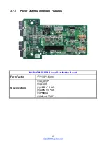
5. Power Cable
Summary of Contents for GC68-B8036
Page 1: ...1 http www tyan com GC68 B8036 GC68A B8036 Service Engineer s Manual ...
Page 2: ...2 http www tyan com ...
Page 33: ...http www tyan com 33 1 5 5 Chassis Dimensions ...
Page 34: ...http www tyan com 34 1 5 6 Block Diagram S8036 ...
Page 36: ...http www tyan com 36 NOTE ...
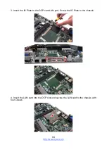
Page 42: ...http www tyan com 42 4 Use a screw driver to fasten the rear top cover ...
Page 47: ...http www tyan com 47 Memory Population table ...
Page 53: ...http www tyan com 53 5 Insert the drive tray into the chassis and close the lever ...
Page 55: ...http www tyan com 55 4 Insert the drive tray into the chassis and close the lever ...
Page 60: ...http www tyan com 60 4 Insert the M 2 card into the slot Pull the latch to lock the M 2 card ...
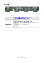
Page 64: ...http www tyan com 64 Front ...
Page 66: ...http www tyan com 66 3 Fasten the chassis ear to the front surface of chassis ...
Page 68: ...http www tyan com 68 NOTE ...
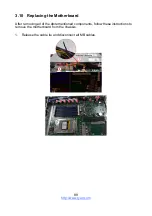
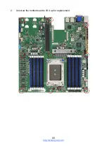
Page 90: ...http www tyan com 90 2 Unscrew the motherboard to lift it up for replacement ...
Page 100: ...http www tyan com 100 BIOS Temp Sensor Name Explanation ...