Operator’s Manual 2020 0217 ENG
18
06
Disassembly and Reassembly
2. Place the end plate onto the blower housing.
Tighten the end plate securely to the housing.
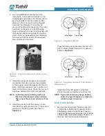
Press the seal assembly onto the rotor until
the assembly bottoms on the rotor. Continue
the process until both seal assemblies are
installed. Press the oil shield into place.
Figure 6-6 – Seal Assembly Installed into End Plate
OTE:
N
The oil shield is part of the seal assembly
but must be pressed on after seal
assembly is installed. On lip seal units,
the seal must be pressed into the seal
housing after the end plates have been
installed onto the housing and before the
slinger is installed on the rotor shaft.
3. Install the bearing shields into the end plate.
Press the bearing into the end plate until the
bearing bottoms to the shoulder of the end
plate. Install the gasket and the extension
cover, and tighten securely to the end plate.
4. Install the drive end spacer onto the rotor
shafts. Position the oil slinger assembly onto
the drive shaft of the blower. Install the oil
slinger assembly onto the driven rotor. Install
rotor washer and bolt. Tighten the bolt securely
to the shaft.
5. Install O-ring into drive end cover. Install the
drive cover onto the extension cover. Tighten
the cover securely to cover the extension.
Install the drive shaft seal into the drive cover.
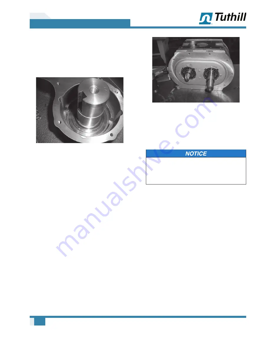
Figure 6-7 – Extension Cover Installed Drive End
6. Install the pipe plugs and oil sight glasses into
their proper locations, which are determined by
the direction of
fl
ow of the blower.
When installing drive shaft seal, use care not
to damage the lip of the seal on the keyway
of the drive shaft. Make sure keyway is free of
burrs and sharp edges.
Checking Interlobe Clearance
1. The outer gear shell is fastened to the
inner hub with four cap screws and located
with two dowel pins. Adding and removing
shims between the gear shell and the inner
hub moves the gear shell axially. The helix
causes the gear to rotate, which changes the
clearance between the rotor lobes. Adding
a shim of 0.030 in. thickness will change the
rotor lobe clearance by approximately 0.009 in.
The timing shim is formed from a number of
0.003 in. shims that have been laminated
together. They are easily peeled off as
necessary or added to correct timing. Use
feeler gauges to check the clearance at AA
(right-hand reading) and BB (left-hand reading)
(see Figure 6-1)
. The clearance should be
adjusted so they are as equal between all
lobes as possible – usually between 0.002 and


