Operator’s Manual 2020 0217 ENG
15
DISASSEMBLY
OTE:
N
Before removing any parts, match-mark
each component with a punch. This will
allow the blower to be reassembled in the
same position. Match-mark the covers,
end plates, housing, cover extension, and
both rotors.
1. Remove oil drain plugs and vent plugs from
both ends of the blower.
2. Remove the drive key from the drive shaft.
Remove the gear end cover. Remove the drive
end cover. This is best accomplished by using
two small pry bars at the dowel pins. Tap on
the cover with a mallet while putting pressure
on the cover with the pry bar. The cover
will slowly move off the dowel pins. Inspect
the seal area on the drive shaft for grooves
and burrs. Remove the drive shaft seal from
the drive end cover. Remove the oil slinger
assemblies.
3. Remove the bolts and washers from the rotor
shafts on the gear end. Remove the timing
gear from the rotor shaft by using a gear puller
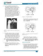
(see Figure 6-1)
. Rotate the timing gear to the
right and left, 3 teeth each direction from the
timing marks on the face of the gears, as the
gear is being removed. Inspect the gear teeth
for wear and pitting. Inspect the rotor shaft
keyway for wear and damage.
1”
2 5/
8”
5 1/
4”
2”
15/16”
1 7/8”
3/4”
Drill Ø 11/16”
Tap 3/4” - 16 UNF
7/16” × 1” Slot
(Thru)
Snap-On
P/N CJ66-15-3
or equivalent
Snap-On P/N CJ83-3
or equivalent
Figure 6-1 – Gear Puller
Blower rotors must rotate freely in order for
timing gears to be removed correctly. If blower
rotors do not move freely both timing gears
must be pulled simultaneously. If gears are
removed improperly, this will cause damage to
the rotor keyways and possibly to the timing
gears.
4. Remove the bolts from the extension covers.
Using pry bars and a mallet, slowly remove the
extension cover from the gear end and drive
end plates as described in step 2. Remove the
gasket from the end plates on both the gear
end and drive end.
DISASSEMBLY AND REASSEMBLY
06


