Operator’s Manual 2020 0217 ENG
17
06
Disassembly and Reassembly
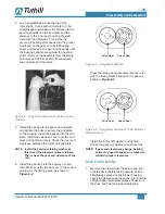
4. Lay a straightedge across the top of the
rotor shafts. Put a depth micrometer on the
straightedge and measure the distance to the
bearing shoulder on the end plate and the
distance to the inner seal housing shoulder.
Calculate the difference. This will be the
amount of bearing shim needed for the proper
clearance on the gear end. Install bearing
shims and press in the gear end bearings until
the bearing bottoms are against the bearing
shims. Remove the assembly from the
fi
xture
and remove 0.006 in. of shim from between
the end plate and the rotors.
Figure 6-3 – Using Depth Micrometer to Determine End
Clearance
5. Install the housing to the gear end end plate,
and tighten the bolts to secure the end plate
to the housing. Install the gasket onto the end
plate. Install the extension cover onto the end
plate and tighten securely. Check the gear end
clearance between the rotors and end plate.
OTE:
N
Install the bearing retaining washer at
this time if the blower requires retainers.
Then, check the gear end clearance of the
unit.
6. Install the gear key into the keyway of each
rotor. Make sure the keyways are in the correct
position for the timing gears, as shown in
Figure 6-4
.
Drive Gear
Driven Gear
Figure 6-4 – Timing Marks Matched
Press the timing gear assembly onto the rotor
with the timing marks aligned on the gear as
shown in
Figure 6-5
.
Drive Gear
Driven Gear
Figure 6-5 – Timing Marks Advanced 3 Teeth (Reference
Marks Matched)
Install the rotor shaft washer and tighten.
Check the gear end clearance and record it.
OTE:
N
If gear end clearances change, bearing
shims may need to added or removed to
maintain proper clearances.
Drive End Assembly
1. Remove the blower from the
fi
xture and turn
until the drive shaft is facing upward. With a
straightedge placed on the blower housing,
check the clearance between the rotor and the
straight edge using feeler gauges. Make sure
the drive end has the proper clearances.


