5
Water Liquid
Cooling
Instructions
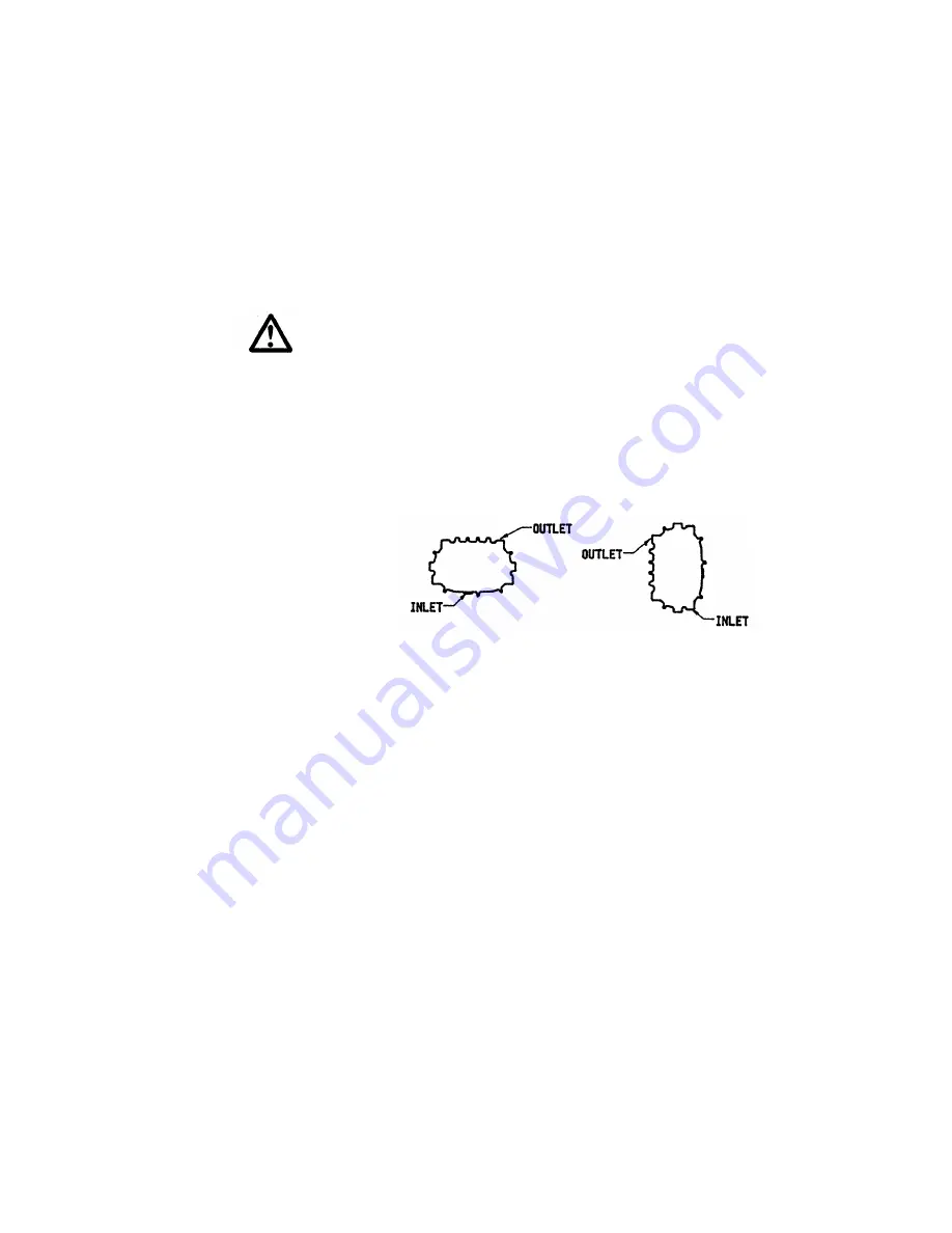
Entrance into the water jacket cavity is through any of the (5) 1”
NPT cooling connection holes in each end plate. For best results,
the cooling liquid should be introduced at the bottom of the end
plates and exits at the top in a diagonal direction as shown below
COOLING WATER SPECIFICATIONS
Flow rate: Depending on operating conditions, 1/2 to 1 gallon per
minute will be required for both end plates.
Maximum Pressure: 75 PSIG
Kinney KV-100 oil is recommended for use on boosters with typical
vacuum applications. Consult Tuthill Vacuum Systems on oils for
use where hazardous or chemically active materials may be present.
Add vacuum oil to the booster in the quality shown in
Specifications on page 2. The oil level must be maintained within
the notched area of the sight glass. See figure 2.
WARNING:
Never attempt to change or add oil while booster is
running. Failure to heed this warning could result in damage to the
equipment or personal injury.
Piping Connections
Manifolding should be no smaller than the pump connections in
order to minimize restrictions to gas flow. Accurately align the
mating flanges to the inlet and discharge manifolding to prevent
distortion of the booster housing. Temporarily fit a fine wire mesh
filter at the suction port if solid particles are likely to be entrained
into the air stream and remove the filter when particles no longer
appear. This is especially desirable on new installations and when
manifolds have been welded. The manifolding to and from the
booster should be fitted with flexible connections to isolate
vibrations, absorb expansion and contraction due to thermal
change, and to absorb misalignment differences. If the booster is to
be water cooled, connect a clean supply to the ¼” NPT connection
on the seal adapter housing adjacent to the drive shaft. The drain
line will be connected on the bottom of the non-drive end reservoir,
see Figure 3 for connection locations.


