18
DISASSEMBLY
KMBD-540
KMBD-720
KMBD-850
KMBD-1600
KMBD-2000
KMBD-2700
1) Disconnect cooling water lines (274 & 181). Do not disturb the
large hex head screw (97). If it is removed, loosened, or water is
detected in drain oil, the coil assembly must be retested as
described in the assembly procedure.
2) Drain oil from both ends of booster and remove port fittings (38
or 48).
3) Remove motor and drive coupling.
4) Remove bolts (93) and take off seal housing (91) using jack
screws.
5) Remove cover (6), mating ring (76) will come off with cover.
6) Remove drive shaft screws (66) and locks (65). Tap shaft lightly
to remove.
7) Remove gear lock nuts and washers (35 & 36). Models KMBD-
850C, 1200C, 1600C, 2000C, and 2700C (horizontal flow series,
top drive only). Remove cap screws (396), washers (136 & 80),
and oil slinger (20) if furnished. These items are not shown on
exploded view but are listed on parts list.
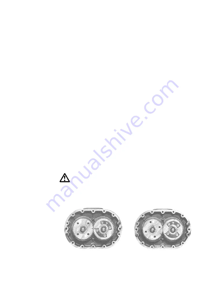
8) Position the timing gears for pulling by first matching the timing
marks on the gears. See Figure 10A. Turn the drive gear
clockwise five teeth and mark a matching reference line on each
gear as shown in Figure 10B. The rotor lobes are now in their
most open position. Using a gear puller, the driven gear (left
hand helix) may now be removed without jamming the rotors.
This gear is in two parts – the gear rim and hub. It is not
necessary to disassemble. Do not allow the gears to move from
matched reference line while pulling. Use a light rocking motion
while pulling the gear to insure that the lobes have not jammed.
WARNING:
Failure to properly pull this gear could result in
damage to rotor keyway or a bent rotor shaft. Never use
excessive force.
9) Remove drive gear. It is not necessary to remove keys from rotor
shafts.
Figure 10A
Figure 10B


