[16]
7.
SENSOR ALIGNMENT PROCEDURE
1) To start, make sure there are no sensor obstructions in the lane.
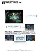
2) Verify that the vertical green LEDs on the PIO labelled beam 1-20 are lit up. If
any of the beams 1-20 are off, that means those receiver sensors are not making
contact with the transmitters.
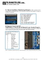
3) If you have the Infinity software and your lanes are wired and set up, you can
verify sensor alignment via the Lane Diagnostic screen. Beams 1-20 should be
displaying a green circle if properly aligned.
4) If one of the sensors is out, then either the transmitter or the receiver beam will
need adjustment. Moving the sensor left and right can be done by gently bending
the aluminum bracket. Be careful not to over adjust the sensor to be aimed at a
different number sensor. Adjusting the sensor vertically should be done by
loosening one of the screws that mount the sensor to the sensor bracket,
adjusting, and then tightening in place.
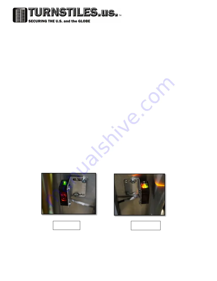
5) During adjustments, look for the orange LED on top of the receiver sensor to
indicate that the receiving sensor is making contact with the transmitter.
6) After all beams are making contact, install pedestal skins one at a time and ensure
that sensor alignment is maintained. If a sensor goes out while installing the
sensor skins, remove the skin and readjust as needed.
7) If alignment is difficult in the daytime, the sensors can be easily aligned in the
darkness. If a dark room is not an option, a tarp may be necessary to block the
light from the lane during alignment.
8) If the RLC is available, and after all skins are installed on the pedestals, verify that
all of the sensors are still making contact in the Lane diagnostic screen.
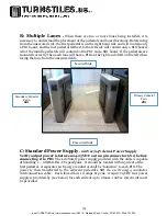
Transmitter
Receiver
www.TURNSTILES.us / www.entrapass.com / 8641 S. Warhawk Road, Conifer, CO 80433 / 303-670-1099

