background image

www.turck.com

 • 1-800-544-7769


•  Fax: (763) 553-0708


•  TURCK  •  Minneapolis, MN 55441 

 41

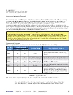
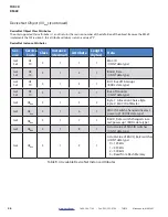
Supported Instance Attributes (continued) 


Attrib. ID  Access

Name

Data Type Description

16#01 - 1

Get

Number of 

Attributes

USINT

Number of supported Attributes = 21

16#02 - 2

Get 

Attribute List 

Array of 

BYTE

List of supported Attributes = 01, 02, 0A, 0B, 0C 

…71hex

16#0A - 10

Get 

Position Value 

Signed 

DINT 

Current position value

16#0B - 11

Get 

Position Sensor 

Type 

WORD 

Specifies the device type  

1 = Single turn absolute rotary resolver

2 = Multi-turn absolute rotary resolver

16#0C - 12

Set 

Direction 

CountingToggle 

BOOLEAN 

Controls the counting direction:  

0 = CW  1 = CCW

16#0E - 14

Set 

Scaling Function-

Control 

BOOLEAN

Enables Scaling function  

0 = OFF  (65,536 counts per turn)

1 = ON  (Scaling set by Measuring Units

                per Span, attribute 10hex)

16#10 - 16

Set 

Measuring Units 

per Span

(Counts per Turn)

UDINT 

Resolution for one revolution:

1 to 65,536 counts per turn

16#11 - 17

Set

Total Measurement 

Range

UDINT

Counts before roll over to zero .

Single Turn RM-89:  Range of 0, 2 to 65,536

Multi-turn RM-89:  Range of 0, 2 to 268,435,455

16#13 - 19

Set 

Preset Value 

DINT 

Sets the position to the specified value . Calculates an 

internal offset that will be saved to the non-volatile 

storage if Save service (code 16#16) is issued .

16#18 - 24

Get 

Velocity Value 

DINT

Current speed . The value is in the format specified by 

attribute 16#19

Table continued on next page

Summary of Contents for DeviceNet RM-89

Page 1: ...USER MANUAL MA1007 REV B Published 4 15 2015 RM 89 DeviceNet Resolver...

Page 2: ...Contents About this Manual 3 Chapter 1 Introduction to the RM 89 4 Chapter 2 Installation 15 Chapter 3 RSNetWorx For DeviceNet 20 Chapter 4 I O Messaging Commands 30 Chapter 5 Explicit Messaging Comm...

Page 3: ...ics are Status LEDs Power Requirements Resolution Response Time Accuracy Mechanical Characteristics data includes Package Size Connector Location Dipswitch Location and Setting Housing Material Shaft...

Page 4: ...he RM 89 resolver based resolvers for DeviceNet are designed for use with the DeviceNet thin cable media and mate with the DeviceNet eurofast M12 connectors DeviceNet thin cable media is commonly used...

Page 5: ...M Time Stamp The time stamp is an unsigned double integer value with an interval of 100 nanoseconds It will roll over every 429 4967296 seconds The time stamp can be used to verify active communicatio...

Page 6: ...n 4 096 turns 12 bit Direction of Increasing Counts Default of CW increasing when looking at the shaft Programmable to CCW increasing over the DeviceNet network Preset Position Position can be preset...

Page 7: ...in sec2 6 00 X 10 4 Max Operating Speed 6000 RPM max Max Shaft Loading Axial 20lbs 89N Radial 40lbs 178N At specified max loads minimum bearing life is 2X10⁹ revolutions Operating Temperature 40 F to...

Page 8: ...s current posi tion value For example assume a 28 bit RM 89 with its default of 65 536 counts per turn If the current position value is 100 000 and you change the Direction Counting Toggle parameter t...

Page 9: ...by the Counts per Turn parameter and the number of turns the RM 89 can encode If the Total Measurement Range is non zero it places an upper limit on the position value and the Preset Value parameter...

Page 10: ...tal Measurement Range quotient is a real number the RM 89 will power up with the correct position value as long as the shaft is rotated less than half of the complete span of the resolver while power...

Page 11: ...he RM 89 can transmit velocity data over the network in addition to position data This parameter sets the units of measure for the velocity data This integer parameter has four fixed options 16 1F04 7...

Page 12: ...fset to Flash memory Absolute position applications will usually preset the position during machine installation and commissioning The Save to Flash command is then issued once to store the internal o...

Page 13: ...ter 5 Explicit Messaging Commands starting on page 31 These commands are Program Parameters Preset Position Save to Flash Restore from Flash Return to Factory Defaults Reset Device Factory Default Set...

Page 14: ...14 www turck com 1 800 544 7769 Fax 763 553 0708 TURCK Minneapolis MN 55441 TURCK RM 89 Notes...

Page 15: ...re changes to the switch settings take effect DeviceNet Bus Address The bus address is set with the two rotary switches When the RM 89 is in the orientation shown in figure 2 1 the switch for the tens...

Page 16: ...nk of two DIP switches Table 2 2 below shows the settings for the three supported bus speeds Note that the all devices on the DeviceNet network must have the same bus speed On power up if the bus spee...

Page 17: ...ng communications between the other devices You also have the option to install a terminator on the Bus Out connector of the RM 89 See TURCK s full line of network media connectivity Replacing the Plu...

Page 18: ...t Connector Pinouts Table 2 5 Suggested Mating Connectors BUS IN OUT B 8151 0 PG9 DNET BUS IN mating connector A coded female straight Screw terminal connections 6 to 8 mm dia cable Plastic body IP67...

Page 19: ...mory The position can also be preset over the network but using the push button may be easier in some applications Note Once the position is reset to zero the plug must be re installed and securely ti...

Page 20: ...file before it can be used to configure the RM 89 The EDS file for the RM 89 can be found on the TURCK website at www turck com The file for the DeviceNet RM 89 is a ZIP file that you will have to ex...

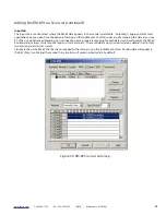
Page 21: ...TURCK Resolver Add the RM 89 by a double click on the icon or drag and drop into the network view Setting General Properties Double clicking on the icon in the network view will bring up the property...

Page 22: ...When on line parameter values are written to the RM 89 when you click on the Apply or Download to Device buttons Note Parameters that are downloaded to the RM 89 are stored in RAM memory and will be l...

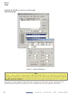
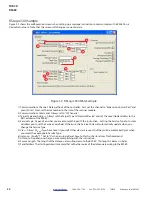
Page 23: ...everal minutes Click on the RM 89 in the graph window Click on Device in the menu bar and then select Class Instance Editor The Class Instance Editor opens as is shown in figure 3 3 1 In the Service C...

Page 24: ...message The execution was completed in the Receive Data text box Note These values are not automatically saved in Flash after they have been reset with this command If you want the parameters to be at...

Page 25: ...ed Refer to the documentation that came with your scanner to add it to your network The 1756 DNB is used in this example Once the scanner is added to the network double click on it to open its Propert...

Page 26: ...sly A single bit will be assigned to the RM 89 in the output data Set this bit to force the RM 89 to update its data By default the Polled communications method is enabled and the RM 89 uses eight byt...

Page 27: ...the data as you see fit When using Advanced Mapping you will need to create a separate mapping for each data word transferred by the RM 89 Position data is always thirty two bits long and starts at wo...

Page 28: ...0 is mapped to Input word 3 offset 3 0 You can also choose not to map data from the RM 89 For example you can choose to map only position data and not velocity data by mapping only the first thirty t...

Page 29: ...9 is added to your scanner the next step is to save the network configuration In RSNetWorx for DeviceNet click on File Save Navigate to a directory that will be available to your RSLogix software type...

Page 30: ...DINT value The remaining four bytes are also a double integer value that defaults to transmitting the velocity data Parameter values and other data can be transmitted in place of the velocity data by...

Page 31: ...Set the command byte to a value of 20hex 6 Hold this value until you are sure the scanner module has transmitted the command byte to the RM 89 7 Set the command byte to a value of D0hex The RM 89 will...

Page 32: ...n your RSLogix program by using a custom assembly instance Explicit messaging uses message instructions that are available on platforms supported by the RSLogix 500 and RSLogix 5000 software packages...

Page 33: ...f you have to set it yourself Other classes are used but they will be automatically set when you select the appropriate Service Type 4 Instance Usually 1 Set to 0 when issuing a Reset Save to Flash or...

Page 34: ...f the RM 89 4 Service Type Depends on what you are accomplishing with the instruction Setting the Service Type to Custom will allow you to set the Service Code field Otherwise the Service Code will au...

Page 35: ...n 1 Enable Scaling Function The number of counts per turn is set by the Measuring Units of Span parameter below 2 2 Counts per Turn Sets the number of counts generated over a single turn if the Scalin...

Page 36: ...alled Send Address Save To Flash Instruction This instruction saves parameter values and the internal position offset to Flash memory Additional data is not sent with this instruction Set data length...

Page 37: ...k Reset Device Instruction This instruction forces the RM 89 to perform a hardware reset Network communications will be lost momentarily and all parameter values will be restored from Flash memory The...

Page 38: ...38 www turck com 1 800 544 7769 Fax 763 553 0708 TURCK Minneapolis MN 55441 TURCK RM 89 Notes...

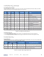
Page 39: ...89 using the custom instances as explained in the previous two chapters because it will greatly simplify your PLC programming The only reasons to use the Position Sensor Object is if you need extreme...

Page 40: ...attributes implemented by the RM 89 Table 5 10 below describes the Data Type values used in this table Note When programming these instances always use a Class Code of 16 23 Table 5 10 Explanation of...

Page 41: ...counting direction 0 CW 1 CCW 16 0E 14 Set Scaling Function Control BOOLEAN Enables Scaling function 0 OFF 65 536 counts per turn 1 ON Scaling set by Measuring Units per Span attribute 10hex 16 10 16...

Page 42: ...n Span UDINT Physical resolution of the single turn resolver sensor 16 2B 43 Get Number of Spans UINT Maximum number of revolutions that could be measured 16 2C 44 Get Alarms WORD Indicates a malfunct...

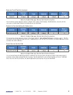
Page 43: ...pported Alarms 16 2C Alarms and 16 2E Alarm Flag indicate something about the alarms supported by the RM 89 16 2D Supported Alarms Reading this attribute returns a value of 3 indicating that the Posit...

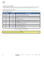
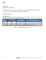
Page 44: ...4hex Supported Services The following table lists the services implemented by the RM 89 for the Assembly Object The services that are implemented only on the Class level not on the Instance should add...

Page 45: ...r the DeviceNet Object The services that are implemented only on the Class level not on the Instance should address Instance 0 Service Code Implemented Service Name Description of Service Class Instan...

Page 46: ...Instance decimal Attribute Length bytes Data Get Set 0E 10 3 1 1 1 MAC ID USINT data type Get Set 0E 10 3 1 2 1 BAUD_Rate USINT data type Get Set 0E 10 3 1 3 1 BOI Bus off Interrupt BOOL data type Get...

Reviews: