background image


USE AND OPERATION 


26/46 

   561379 - IS16/02 - EN 


7.3 

CHECKS BEFORE SWITCH-ON 

Carry out the following checks: 
 
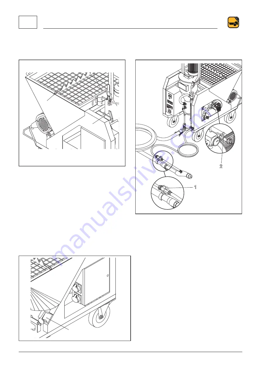
- Check that the protection grid on the hopper is properly secured with the screw shown in the figure (FIG.16-REF.1). 
 

1

2

3

3

1

1

2

2


FIG.16                                                                                               FIG.17 
 
-  Check  that  the  mixing  unit  is  properly  locked  (FIG.16-REF.2)  and  the  gear  motor’s  support  closing  hook  (FIG.16-REF.3)  is 
firmly closed. 
- Check that the air cock (FIG.17-REF.1) of the gun is open and the water service cock (FIG.17-REF.2) is closed. 
- Check that the dispenser switch, the main disconnecting switch and the water pump switch are at zero. 
 
- Connect the power cable to the socket (FIG.19-REF.1) on the machine’s frame. 
 

1


FIG.19 

Summary of Contents for GIOTTO MONO

Page 1: ...Serial number Year USE AND MAINTENANCE MANUAL GIOTTO MONO IS16 02 561379 EN ORIGINAL ...

Page 2: ...THIS MANUAL IS PROPERTY OF TURBOSOL ANY TOTAL OR PARTIAL REPRODUCTION IS STRICTLY FORBIDDEN ...

Page 3: ...RIPTION 9 3 1 NAME OF MACHINE 9 3 2 DIMENSIONS OF MACHINE 10 3 3 TECHNICAL DATA 10 3 4 INTENDED USES 10 3 5 PRODUCTS USED FOR PROCESSING 11 3 6 NAME OF COMPONENTS 12 4 TRANSPORT AND HANDLING 13 4 1 TRANSPORT 13 4 2 LIFTING 13 5 INSTALLATION 15 5 1 PLACEMENT 15 5 2 HOSES 16 5 3 COUPLINGS 16 5 4 CONNECTIONS 17 6 SAFETY 21 6 1 SAFETY DEVICES USED 21 6 2 SAFETY SIGNALS 22 LABEL 22 DESCRIPTION 22 6 3 P...

Page 4: ...ING UNIT 33 7 8 IMPORTANT WARNINGS 34 8 MAINTENANCE 37 8 1 OPERATOR RESPONSIBILITY 37 8 2 QUALIFIED PERSONNEL RESPONSIBILITY 37 9 DEMOLITION 39 9 1 MAIN WARNINGS 39 10 TROUBLESHOOTING 41 10 1 MATERIAL DOES NOT COME OUT OF THE GUN 41 10 2 BLOCKING THE PUMP 42 10 3 FUSES OVERLOAD CUTOUT TRIPPING 42 10 4 OTHER PROBLEMS 42 10 5 OPERATOR INTERVENTION 43 11 OPERATOR RESPONSIBILITY 45 11 1 RESPONSIBILITY...

Page 5: ...CE DECLARATION 1 561379 IS16 02 EN 5 46 1 CE DECLARATION 1 1 CE DECLARATION OF CONFORMITY An original copy of the CE Declaration of Conformity is supplied separately from the manual ...

Page 6: ...1 CE DECLARATION 6 46 561379 IS16 02 EN ...

Page 7: ... in force in the country of use The Manufacturer shall not be responsible for any damages resulting from changes made arbitrarily to the machine Users are advised to take note of the machine s serial number it must be presented along with every request for technical assistance or for spare parts and will facilitate processing such requests This manual reflects the latest information available at t...

Page 8: ...ired in this way along with great attention to quality constitutes the fundamental guarantee for the manufacturing of machines with long duration great reliability and reduced management costs MAINTENANCE AND CARE Proper maintenance and care are essential for the machine to work as designed It is therefore extremely important that users respect the recommended maintenance intervals and carry out a...

Page 9: ...the nameplate as well as its power rating The meaning of the symbols used are as follows 1 Machine series 2 Machine model 3 Machine serial number Position of the CE mark plate The CE mark plate FIG 02 REF 1 is affixed to the mixer chamber Position of the machine serial number The machine s serial number FIG 02 REF 2 is punched onto the mixer chamber as well as on the nameplate 1 2 FIG 02 ...

Page 10: ...p mm 5 Delivery distance approximate m 15 Hopper capacity l 110 Permissible environmental temperature C 0 35 Guaranteed sound power level LwA dB 101 Guaranteed sound pressure level LpA dB 78 Mortar pump gear motor Power kW 3 Performance 1 l min rpm 12 225 2 14 5 270 3 18 300 Dispenser gear motor Power kW 0 25 Speed 1 rpm 6 2 7 5 3 9 Water pump Power kW 0 6 Flow rate l min 45 Head m 43 Pressure swi...

Page 11: ...TECHNICAL DESCRIPTION 3 561379 IS16 02 EN 11 46 3 5 PRODUCTS USED FOR PROCESSING Cement or gypsum based dry ready mixed products GIOTTO is not suitable for processing traditional mortars ...

Page 12: ...d names of the main components that make up the machine 5 10 4 7 3 9 2 1 13 11 6 12 8 FIG 03 KEY 1 Frame 2 Hopper 3 Protection grid 4 Main gear motor 5 Mixing chamber 6 Mixer 7 Dispenser 8 Dispenser gear motor 9 Electromechanical control board 10 Water pump 11 Flow meter 12 Pump stator screw 13 Compressor ...

Page 13: ...separately gear motor mixer mixing chamber unit compressor frame with hopper Motoriduttore miscelatore Motor reducer mixer Gruppo camera di miscelazione Mixing chamber unit Compressore Compressor Telaio con tramoggia Frame with hopper 1 FIG 04 GIOTTO cannot be towed on the road GIOTTO must be loaded arranged and transported on a vehicle in compliance with the highway code in force 4 2 LIFTING GIOT...

Page 14: ...4 TRANSPORT AND HANDLING 14 46 561379 IS16 02 EN ...

Page 15: ...lowed longitudinal and transversal slope is 5 FIG 05 max max max max FIG 05 Before starting make sure the wheel with brake is locked There must be a minimum clear floor space around the machine FIG 06 free from any obstructions and with a walkway without any holes or dangerous protrusions 140 cm 130 cm 130 cm 140 cm FIG 06 ...

Page 16: ... by companies expressly authorised by the former In no case shall TURBOSOL PRODUZIONE S p A be liable for damage to persons or things caused by the use of non original hoses or couplings 5 3 COUPLINGS Check couplings are always effective and clean Camlock fittings Connect the hoses ensuring the presence of rubber gaskets FIG 07 REF 1 fully tighten the levers FIG 07 REF 2 Always connect the longer ...

Page 17: ... s electrical control board with a H07RN F marked neoprene coated cable 2P T with a minimum section of 2 5 mm for distances up to 20 m 4 mm for distances up to 35 m 6 mm for distances up to 50 m Using an electrical cable with inadequate section compromises machine operation Connect the power cable to the socket FIG 08 REF 3 1 2 3 FIG 08 Other connections Connect the material hoses FIG 09 REF 1 to ...

Page 18: ...opened FIG 11 REF 2 The water flow used can differ from the above indications in relation to the length of the conveying hose line wear of the pump screw and stator and experience of the user The water entering the water pump must be clear and free of impurities If the water network does not provide the required water flow use a 200 litre container with compensation function The container must hav...

Page 19: ...INSTALLATION 5 561379 IS16 02 EN 19 46 1 2 FIG 11 ...

Page 20: ...5 INSTALLATION 20 46 561379 IS16 02 EN ...

Page 21: ...pump you must reactivate the function PNEUMATIC SYSTEM PRESSURE RELIEF VALVE Avoid circuit overpressure TAMPERING WITH EXCLUDING AND OR REMOVING ANY OF THE SAFETY DEVICES ON THE MACHINE IS STRICTLY PROHIBITED REPLACING ANY SAFETY DEVICE OR ONE OF ITS COMPONENTS WITH NON ORIGINAL SPARE PARTS IS STRICTLY PROHIBITED IT IS COMPULSORY TO CONSTANTLY MAKE SURE THAT ALL SAFETY DEVICES INSTALLED ON THE MAC...

Page 22: ...s B It is mandatory to read the instruction manual before starting to operate TAB 04 It is compulsory to always keep the safety signals clean to guarantee good visibility It is compulsory to replace the deteriorated safety signals requesting them from the manufacturer It is strictly forbidden to remove or damage the safety signals applied on the machine A A B FIG 14 ...

Page 23: ...ce in the country where the machine is used Employers managers and operators in charge must know and apply said standards USING THE PERSONAL PROTECTIVE EQUIPMENT INDICATED BY THE MANUFACTURER IS COMPULSORY TAB 05 MANDATORY SIGNS DESCRIPTION IT IS MANDATORY TO PROTECT THE EYES IT IS MANDATORY TO PROTECT HEARING IT IS MANDATORY TO PROTECT THE HANDS IT IS MANDATORY TO PROTECT THE FEET TAB 05 ...

Page 24: ...le the machine is in operation Do not use the machine without the protection grid or sleeve properly assembled and fitted ELECTRICAL PARTS Never operate with the electrical control board open Do not direct intense water jets on the electrical control board or on the electrical sockets 6 5 SAFETY WARNINGS The machine must never operate if the hose is not connected to the delivery flange and to the ...

Page 25: ...nveyed to the gun the mixture formed by air and mixture comes out from the gun in the form of a jet The angular width of the jet can be regulated by axial displacement of the nozzle FIG 15 REF 1 by the air inside the gun and or by replacing the deflector FIG 15 REF 2 The gun is fitted with a cock FIG 15 REF 3 that intercepts the air flow its opening and closing controls the machine start and stop ...

Page 26: ...FIG 16 FIG 17 Check that the mixing unit is properly locked FIG 16 REF 2 and the gear motor s support closing hook FIG 16 REF 3 is firmly closed Check that the air cock FIG 17 REF 1 of the gun is open and the water service cock FIG 17 REF 2 is closed Check that the dispenser switch the main disconnecting switch and the water pump switch are at zero Connect the power cable to the socket FIG 19 REF ...

Page 27: ...USE AND OPERATION 7 561379 IS16 02 EN 27 46 After any repair or maintenance work make sure all of the protection devices are put back in place and that no tools are forgotten inside the machine ...

Page 28: ... Speed selector 20 5 Mortar pump inversion 20 6 Water pump On Off 20 7 Dispenser On Off 20 8 Water supplement 20 9 Water pressure indicator 20 10 Voltage presence indicator 20 11 Overload cutout and safety device tripping OTHER CONTROLS FIG REF DESCRIPTION 20 12 Drain valve 20 13 Drain valve 20 14 Auxiliary valve 20 15 Drain valve 20 16 Start stop pneumatic control 20 17 Flow meter valve ...

Page 29: ...switch is ON the following come one the red indicator signals anomalies the blue line presence indicator if the line voltage is sufficient the compressor starts working the green water pressure presence indicator lights up when there is enough pressure in the water system if water is supplied from a drum the green indicator lights up only with the water pump inserted Pour the contents of a bag of ...

Page 30: ...uence 2 seconds on 2 seconds off 2 seconds on 2 seconds off on Adjust the water flow with the cock FIG 23 REF 1 until you have the desired consistency Constantly keep the hopper powered with the material NOTE the normal operating pressure displayed on the pressure gauge FIG 24 REF 1 depends on the material and the length of the hoses used it is useful to regularly check this pressure value to read...

Page 31: ...bling any of the machine s components or accessories Stop the dispenser and continue pumping until only water is output from the gun Stop the material pump Remove the gun and wash it carefully disassembling the deflector FIG 26 REF 2 Make sure the nozzle hole FIG 26 REF 1 is clear if necessary clean it with specific cleaner Disconnect the hoses from GIOTTO and insert a washing sponge into the hose...

Page 32: ...rial pump by putting the main disconnecting switch FIG 32 REF 1 on OFF Remove the scraper FIG 30 REF 1 and clean inside the mixing unit FIG 30 REF 3 with a cloth Re insert the mixer NOTE If there is a risk of frost completely drain the water system Proceed as follows Put the main disconnecting switch FIG 31 REF 1 on OFF Disengage the water pump with the switch FIG 31 REF 6 Disconnect the hose FIG ...

Page 33: ... UNIT Before carrying out this operation stop the material pump with the main disconnecting switch and then disconnect the power socket The operator must be specifically trained to carry out this operation In particular before opening a coupling check the delivery flange pressure gauge to make sure there is no residual pressure in the hoses and in any case when stepped on the hoses must sag Also m...

Page 34: ...ump and extract the screw FIG 35 Grease the screw and the stator mouth with Vaseline DO NOT USE MINERAL OILS AND GREASES BUT ONLY VASELINE Partially insert the screw inside the flared mouth Hit the pump stator screw partially inserted repeatedly on a base that does not ruin the stator e g a piece of wood FIG 36 D FIG 35 FIG 36 7 8 IMPORTANT WARNINGS The operator must be specifically trained to car...

Page 35: ...ced person DISASSEMBLY OF THE HOSE LINE Before disconnecting the hose line make sure it is not pressurised If the line is pressurised disconnect the water hose from the mixing chamber invert the rotation direction of the mortar pump for a few seconds With the hose depressurised put the main disconnecting switch on OFF and then disconnect the hose line ...

Page 36: ...7 USE AND OPERATION 36 46 561379 IS16 02 EN ...

Page 37: ...perations to carry out weekly or every 25 hours Make sure the compressor s air filters FIG 39 REF 1 are clean Make sure the motor gear unit s O rings are intact there must be no traces of grease Operations to carry out monthly or every 100 hours Replace the compressor s air filters FIG 39 REF 1 Use compressed air to thoroughly clean the mixer s main gear motor the dispenser s gear motor the compre...

Page 38: ...8 MAINTENANCE 38 46 561379 IS16 02 EN ...

Page 39: ... When demolishing the machine it is compulsory to follow the standards in force in the country of use Separate the machine parts by type of material plastic rubber iron etc Oils must be delivered to authorised companies who specialise in the disposal of these products ...

Page 40: ...9 DEMOLITION 40 46 561379 IS16 02 EN ...

Page 41: ... gauge indicates a higher pressure than the normal operating pressure In this case Depressurise the hose as described in paragraph 7 8 Turn the machine off Check that the pressure indicated by the pressure gauge on the delivery flange is zero Check that the material delivery hose is not hard and stiff anywhere along its length then disconnect it to release clogging Find where the material delivery...

Page 42: ... OVERLOAD CUTOUT TRIPPING The red indicator on the electrical control board lights up when an overload cutout trips The electrical control board does not work when a fuse blows Turn the machine off Open the electrical control board or reset the tripped overload cutout or replace the blown fuse by referring to the wiring diagram in this manual for the next operations Close the electrical control bo...

Page 43: ...SPRAYING Air system partially obstructed Make sure the air hose is not bent Clean the gun nozzle Water is not reaching the mixing chamber the red indicator lights up to indicate that the overload cutout has tripped Make sure the flow meter cock is not completely closed Make sure the water supply hose to the mixing chamber is not bent GUN SPRAYING IS WEAK Loss of air in line Check the air line and ...

Page 44: ...10 TROUBLESHOOTING 44 46 561379 IS16 02 EN ...

Page 45: ... said Organisations during normal working hours The faulty pieces must be sent to the Manufacturing Company ex works which commits to gratuitously repair or replace those parts that at its undisputable judgement show quality defects The replaced parts remain the manufacturer s property The purchaser is responsible for the material shipment expenses and those relating to servicing by the Manufactur...

Page 46: ...11 OPERATOR RESPONSIBILITY 46 46 561379 IS16 02 EN ...

Reviews: