


8
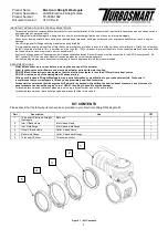
Connecting Your Wastegate
The Turbosmart Electronic wastegate comes unterminated with
7 wires.
Wiring Pinout
Revision B (current)
– Wiring
Colour
Description
1 single core
wire each
Large Gauge Red
Motor A tending towards
0%
Large Gauge
Black
Motor B tending towards
100%
Multi Core
Wire
Red**
5V
Black***
Sensor ground 0V
White
Position Signal 0-5V
Blue
(Rev B Only)
*
Unfiltered Signal Output
(Position Output)
Yellow
(Orange
Rev A)
Temperature Signal 0-5V
*Note:
The Blue (unfiltered position signal) is not required for
use & is for development purposes only.
**
Note:
The 5V red wire has no reverse polarity protection, use
only 5V wired in correctly.
**Note:
The sensor ground must be grounded at the ECU
Sensor ground and
NOT
the chassis.
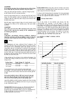
Sensor Voltage Limits
Deg C (Deg F)
Temperature
Sensor
Output (mV)
0 (32)
2630
150 (302)
538
Position Sensor
Target Voltage (V)
Duty Cycle
100% (Open)
0.2-0.6V
~16%
0% (Closed)
4.2-4.60V
~84%
CAUTION!
Turbosmart recommends calibrating the position sensor
before connecting the motor wires to your motor drive.
The two large wires are directly connected to the motor of the
wastegate and need to be connected to high power drives in a
Full bridge configuration like that of an electronic throttle drive
circuit, see your ECU supplier documents for suitable
connections. Turbosmart recommends the eWastegate should
be driven by an External dual H-Bridge, which is at least 20A for
seamless operation.
Connect the small Red Wire to a 5V power source from your ECU
as well as the Black wire to Sensor ground. Connect the white
wire to a 0-5V analogue input on your ecu as well as the orange
temperature sensor signal. The blue wire (Revision B only) is an
unfiltered position output signal for development purposes - This
can be left unterminated.
CAUTION!
Whilst the temperature sensor is not required for operation
it is recommended for activating failsafe protocols.
Ensure all connections are high quality and away from any
heat source.
It is important during the setup of the eGate, that some
precautions are taken to ensure that the unit does not
malfunction. Firstly, the output from the ECU should be
limited to 15%. As well as an inline fuse (5A-10A) or breaker
to protect the eGate. Once correct operation has been
verified the fuse and limits can be removed.
Calibration
CAUTION!
Disconnect the motor wires to prevent accidental spin up.
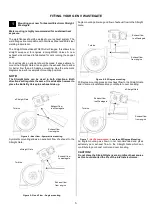
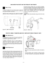
To calibrate the electronic straight gate firstly the manual override
cap must be removed to allow access to the manual override. A
non marking 14mm is required to remove the cap from the body.
Figure 12
– Manual Override
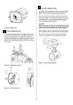
Using a ¼” drive extension with a 5mm socket, turn the manual
override in a clockwise direction with your fingers until the
mechanism stops rotating. In this position the butterfly valve
should be home against the valve seat and will be your 0%
position.
Figure 13
– ¼ Drive extension with 5mm socket manually
adjusting.
3
3
4
3
Valve OPEN
Valve CLOSED
14mm Manual Override Cap


