Turbosmart TS-0565-1002 Quick Start Manual Download Page 4


BASIC TUNING PARAMETERS 

It is important that the basic tuning parameters are discussed with a trained professional, please consult your ECU 
manufacture. There are a few basic parameters that are worth noting.  
 

Motor polarity is important,

 Due to the nature of PID controllers (Proportional-integral-derivative controller) the Electronic 

Straight Gate will be targeting a set position, this will move further away if the motor polarity is wrong as it is trying to reach 
its setpoint.


Current limitations

, it is important that the Current that is driven through the motor is limited to no more than 20amps for 

more than 1 second and 5 amps for more than 5 seconds. It is important that the current values such as the dead band are 
correctly set in the ECU to allow for the motor to only be active if needed.  
 

Sensor Diagnostic limits

 should be monitored for values that are lower than 0.1V and higher and 2.15V with respect to 

the Temperature sensor and 0.1V-4.9V with the position sensor. It is also recommended that safety tuning strategies are in 
place to lower temperatures if the eWastegate internally reaches a temperature of 150degC (302degF). 
 

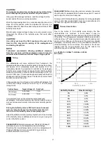
Butterfly Position limits 

should be set to target 0% for butterfly closed and 90% for completely open, Since the design of 

the end stops is biased to operate better with the butterfly in the closed position it is recommended to avoid opening the 
butterfly at full opening. 
 

Boost cut 

should be set


to ensure the safety of your engine a sensible boost cut should be set with in the ECU to control 

any possible over boost issues that could be detrimentally to your engine.  


------------------------------------------------------------------------------------------------------------------------  

WHAT’S NEW 


The new Turbosmart Electronic Straight Gate is Turbosmart’s addition to its electronic wastegate line-up. A new level of control is 
now available with the butterfly valve and offers the option for customers who require another packaging or new level of control.  

Control 

With the introduction of the electronic motor to drive the  Electronic Straight Gate, a new level of control is now available to boost 
control, there is a wide range of tuning strategies that can be implemented to better control boost as well as engine protection. This 
allows the Engine to maintain much better control over the turbocharger. 
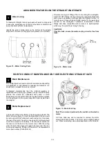
Adjustability 

The straight gate now offers 3 options for the motor and body to be mounted in, this is coupled with infinite possibilities of the body 
and exhaust piping with the weld flanges. So, if you need the  Electronic Straight Gate mounted in the opposite orientation to stop 
fouling with parts within the engine bay, there is an orientation that is suitable for the Electronic Straight Gate to operate in. This mixed 
without the need of having to remove and reassemble due to changes in base wastegate spring pressure the Electronic Straight Gate 
has next level control adjustability of the position of the wastegate butterfly valve. 

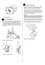
Upgrades and Servicing 

Due to the modular construction, the new range is also upgradeable and completely serviceable, as all components can be removed 
or upgraded. Components have been tested for over one million cycles, so reliability is rock-solid. 

Flow and Thermal Performance 

The new straight wastegate is a world first in its class It features excellent flow properties thanks to our world-leading engineering 
and simulation abilities. Thermal performance is a critical key performance factor within the design of all our products. Thermal stability 
and longevity are further extended with the liquid cooling ports for further thermal performance if required. 


Summary of Contents for TS-0565-1002

Page 1: ... removing the end cap off the actuator Allow for adequate cool airflow around electronic actuator paired with water cooling DO NOT Mount the electronic wastegate so that the electronic actuator is less than 100mm from a heat source DO NOT wrap the body of the wastegate with exhaust wrap Fitting your Electronic Straight Wastegate may require fabrication or modification to your exhaust manifold Turb...

Page 2: ...AINTENANCE 3 TEMPERATURE 3 BASIC TUNING PARAMETERS 4 WHAT S NEW 4 STRAIGHT ELECTRONIC WASTEGATE OVERVIEW 5 FITTING YOUR GEN V WASTEGATE 6 Mounting your new Turbosmart Electronic Straight Wastegate 6 Fitting the Straight Gate 7 Connecting Your Wastegate 8 Tuning 9 ADVANCED FEATURES ON THE STRAIGHT WASTEGATE 10 TROUBLESHOOTING 12 ...

Page 3: ... valve manually set to about the middle of its stroke This will allow for an easier installation The Straight Gate can be used in both directions Please see below for a more detailed and helpful way of installing the Turbosmart Electronic Straight Wastegate MAINTENANCE Turbosmart Electronic Straight Wastegate will require periodic reapplication of spray grease such as Inox MX8 spray grease this is...

Page 4: ...e is Turbosmart s addition to its electronic wastegate line up A new level of control is now available with the butterfly valve and offers the option for customers who require another packaging or new level of control Control With the introduction of the electronic motor to drive the Electronic Straight Gate a new level of control is now available to boost control there is a wide range of tuning s...

Page 5: ...te Overview Outlet Weld flange Outlet V Band Inlet V Band Water Cooling port 1 8 NPT Wiring Loom Inlet Weld Flange Water cooling symbol Figure 2 Electronic Straight Gate Water Cooling Figure 3 Electronic Straight Gate Exploded Manual Override cap 3 x Housing locating screws ...

Page 6: ... place the Butterfly Valve pins exhaust side up Figure 4 Best flow Symmetric mounting Symmetric mounting allows an excellent flow of exhaust to the Straight Gate Figure 5 Good Flow Angle mounting Angle mounting allows a good flow of exhaust flow to the Straight Gate Figure 6 90 Degree mounting 90 Degree mounting gives poor exhaust flow to the Straight Gate and in some circumstances may contribute ...

Page 7: ...ition slide the v band over the flange to allow for the wastegate to be installed Figure 8 Butterfly Valve Pins Using the 3 8 deep socket and a torque wrench Tighten the V Band to 7N m 5 ft lbs Ensure the wastegate is home correctly while torquing the nut to not have a false torque as this will likely contribute to exhaust leaks It is important that the butterfly valve sits slightly open for insta...

Page 8: ...is at least 20A for seamless operation Connect the small Red Wire to a 5V power source from your ECU as well as the Black wire to Sensor ground Connect the white wire to a 0 5V analogue input on your ecu as well as the orange temperature sensor signal The blue wire Revision B only is an unfiltered position output signal for development purposes This can be left unterminated CAUTION Whilst the temp...

Page 9: ...egate Turbosmart recommends that the butterfly valve is only ever driven electronically to the maximum butterfly position of 90 Driving the butterfly valve to 100 will cause increased wear on components such as the electronic motor as it tries to force the butterfly valve to completely open Adjust the calibration to allow plenty of overshoot to the end stops of the butterfly valve recalibrate as a...

Page 10: ...tion In high demand unusually environments it is advisable to increase the service interval Turbosmart recommends that the internal gearbox is regreased with a spray type grease such as Inox MX8 spray grease this should be conducted half yearly or more depending on environment With the top plate removed grease can be sprayed into the small inspection holes located near the magnet Motor Replacement...

Page 11: ...y 30 deg to the body and the current configuration 90 deg to the body The actuator locking pins are 3mm Allen keys that lock the body to the actuator It is important that the butterfly remains in the same position the recommended position is to be just off the valve seat It is also advisable to not to move the manual override during this process CAUTION Moving body and actuator while separated wil...

Page 12: ...rbosmart if this occurs Wastegate fluctuates and fails to find targeted position motor wires may be the incorrect way Swap and test to see Ensure to use sensible current limits to prevent over currenting Wastegate seized Remove cap and manually move butterfly feeling for resistance Wastegate moves but sensor not reading Check connections Boost creeping at high rpm Wastegate flow path is poor waste...

Reviews: