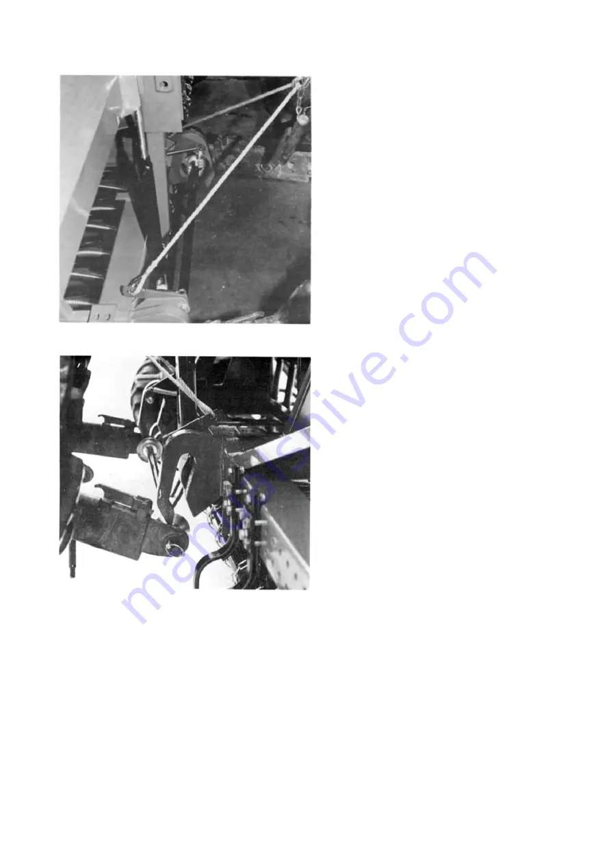
Fig. 4. Detaching the crossbar from the drill.
Fig. 5. Mounting the crossbar to the drill.
Mount all the ropes and cables coming to the cab. The top link is fastened to the lug. The length of
the top link is adjusted by keeping the lid of the machine in a horizontal position when using the
machine.
The hose of the marker changer is connected tot eh single acting hydraulic take off of the tractor’s
hydraulic system. The control valve must then be in the ‘lowering’ position.
During transport the side limiters of the tractor’s lower links are adjusted to a fixed position in order
to prevent lateral swing. In working position the side limiters must be slack.
During the first lifts make sure that the mudguards or other parts of the tractor do not damage the
drill.
During transport the markers can be locked in vertical position, see figures 7 and 8.


