16
Installing warm air ducts
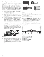
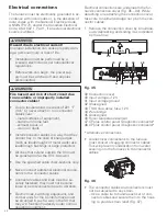
For each warm air duct, the minimum length
in front of the first outlet is 3.3 ft (1 m).
Best heating results are achieved with all ducts
having equal lengths. The longest duct strands
should be attached to the upper warm air outlets
(Fig. 17 – U). We recommend a maximum length
of 3.3 ft (1 m) using the AD 35 warm air duct.
1. Avoid sharp bends or crushed ducts. Small-
est allowable bend radius:
– AD 65: 2.6 in. (65 mm)
– AD 35: 1.4 in. (35 mm)
2. Stretch all ducts and run them directly to
outlets, keeping number and angles of bends
to a minimum.
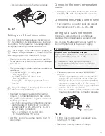
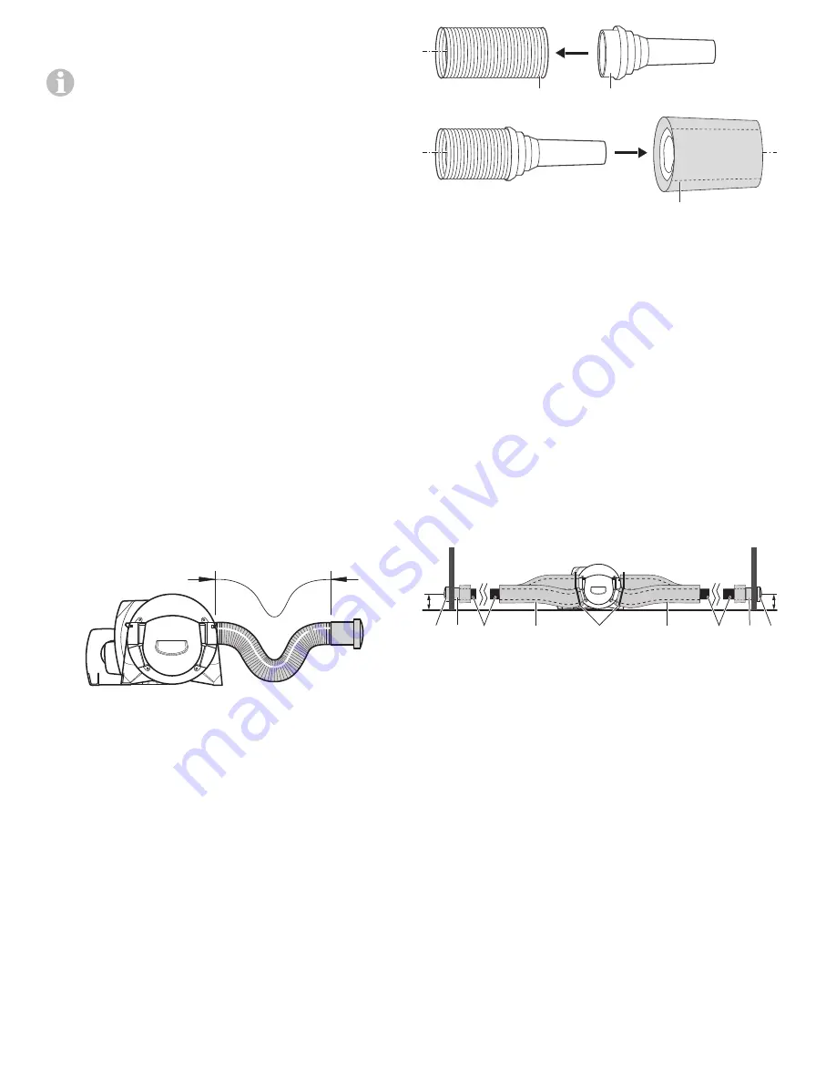
3. To prevent undesirable heating of the vehicle
due to convection (stack effect) while the
water heating mode is activated, create a
siphon near the warm air outlet of the Combi
furnace (Fig. 18). Alternatively, install the
first outlet at a height above the floor not
exceeding:
– the height of the warm air outlet the duct is
attached to; for ducts with a length of more
than 5 ft (1.5 m) in front of the first outlet.
– 4 in. (100 mm) above the floor; for ducts with
a length between 3.3 ft (1 m) and 5 ft (1.5 m)
in front of the first outlet.
3.3 ft (1 m)
Fig. 18
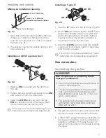
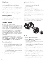
4. Slide the 3 in. insulating sleeve (Fig. 19 – 3)
and cable tie (Fig. 20 – 3) onto the warm air
duct
AD 65
(Fig. 19 – 1). If necessary, use
the tool supplied by Truma (Fig. 19 – 2) to do
this.
1
2
3
Fig. 19
1 Warm air duct
AD 65
2 Tool for sliding the insulating sleeve on to the
warm air duct
3 3 in. insulating sleeve
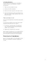
5. Insert the
AD 65
warm air duct (Fig. 20 – 1)
into the furnace’s warm air outlet until it fits
snugly. Metal clips in the warm air outlets
hold the ducts in place.
• Use the cable ties (Fig. 20 – 3) to secure the
insulating sleeve to the
AD 65
warm air duct
(Fig. 20 – 1).
1
2
≤ 4 in. (100 mm)
≤ 4 in. (100 mm)
4
3
5
1
2
4 5
Fig. 20
1 Warm air duct
AD 65
2 3 in. insulating sleeve
3 Cable
tie
4 End outlet nut
EM
5 End
outlet
EN

