


12
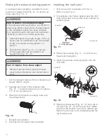
Making the exhaust venting system
An exhaust venting system consists of a com-
bustion-air supply tube (Fig. 10 – 2) and an ex-
haust tube (Fig. 10 – 1).
Risk of carbon monoxide poisoning!
If the exhaust venting system is cut too short,
stress may affect screw joints. Underpressure
in the installation space can allow exhaust
from outside to enter the warm air distributor,
resulting in carbon-monoxide poisoning.
• Carefully select the proper length of the ex-
haust tube for installation; see”Permissible
length of exhaust venting system” on
page 11.
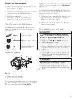
• The exhaust tube (Fig. 10 – 1) must be
10 % longer than the combustion-air
supply tube (Fig. 10 – 2).
Risk of injuries from sharp edges!
• Always wear protective gloves and eye-
wear during installation and maintenance
work.
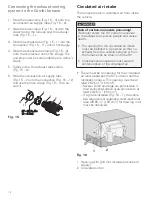
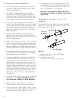
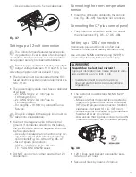
1. Cut the exhaust tube and the combustion-air
supply tube to length.
2. Squeeze each end of the exhaust tube
(Fig. 10 – 1) inward, shortening it by approx.
1 in. (2 cm) at each end.
3. Slide the combustion-air supply tube over
the exhaust tube.
1
2
+10 %
Fig. 10
1 Exhaust tube (inside)
2 Combustion-air supply tube (outside)
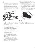
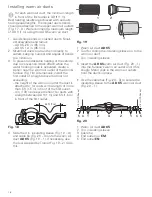
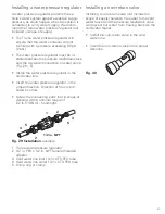
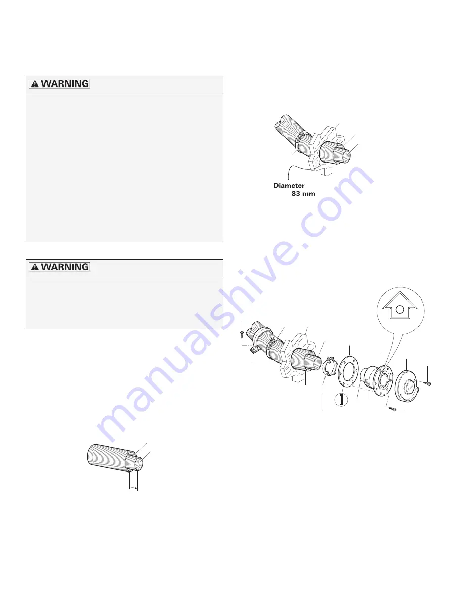
Installing the wall cowl
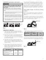
1. Drill a hole with a diameter of 3 1/4 in.
(83 mm); see Fig. 11.
2. If necessary, line hollow spaces near the drill
hole with wood or any other solid material to
attach screws.
1
2
4
Side wall
Outside RV
Inside RV
(
)
3 1/4 in.
Fig. 11
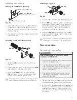
3. Slide a hose clamp (Fig. 11 – 4) over the ex-
haust venting system.
4. Insert the exhaust venting system into the
drill hole.
9
4
1
2
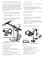
27 – 35 in. lbs
27 – 35 in. lbs
(3 – 4 Nm)
(3 – 4 Nm)
3
6a 6b
6
8
7
5
7
Side wall
Outside RV
Inside RV
10
TOP
Fig. 12
5. Slide the rubber seal (Fig. 12 – 5) onto the in-
ner part (Fig. 12 – 6) of the wall cowl. Make
sure that the smooth side of the rubber seal
faces the wall cowl, with the sealing lips fac-
ing the side wall.


