


9
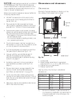
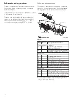
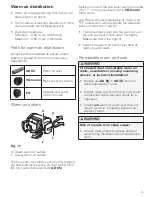
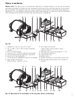
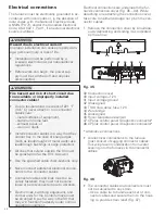
Clearance from combustible materials
Example not to scale.
i
i
TOP VIEW
FRONT VIEW
f
k
g
h
g
Fig. 4b
Consult Fig. 4b for the clearance.
Clearance
in.
mm
f
BACK (Duct Connection)
1
25
g *
)
COMBUSTION AIR DUCT
1
25
h
FRONT (circulation air inlet)
4
100
h**
)
FRONT (circulation air inlet)
2
50
i
LEFT SIDE / RIGHT SIDE
0.5
12
k
TOP
2
50
–
BOTTOM
0
0
–
WARM AIR DUCT insulated
0
0
*
)
Clearance along combustion air supply
tube
**
)
Minimum distance, if gas connection is
not inside the installation compartment
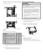
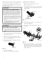
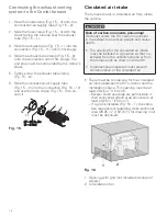
Securing the furnace
Risk of explosion!
An improperly secured Combi furnace can be-
come dislodged in an RV accident and the gas
line can become disconnected.
• The floor or false floor must bear the load
of a secured furnace. Contact the Truma
Service Center on 1-855-558-7862 if you
are unsure whether the floor can bear the
load of the furnace.
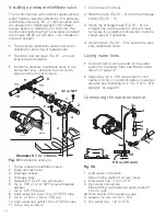
• Use the supplied or equivalent screws
(Fig. 5 – 3).
• DO NOT use screws with a smaller core di-
ameter under any circumstances.
1. Screw both aluminum frame feet (Fig. 5 – 1)
to the floor or false floor.
2. Screw at least one plastic frame foot
(Fig. 5 – 2) to the floor or false floor.
1
1
2
2
Top view
3
Fig. 5
1 Aluminum frame feet
2 Plastic frame feet
3 Panhead self-tapping screws #12 x 1 in.
(5.5 x 25 mm) or equivalent screws (4 screws)


