background image

25

INSTALLATION STEP 12

Connect Door Arm to Trolley

Follow instructions which apply to your door type as
illustrated below and on the following page.

SECTIONAL DOORS ONLY

• Make sure garage door is fully closed. Pull the

emergency release handle to disconnect the outer
trolley from the inner trolley. Slide the outer trolley
back (away from the pulley) about 8" (20 cm) as
shown in Figures 1, 2 and 3.

• Figure 1:

– Fasten straight door arm section to outer trolley

with the 5/16"x1" clevis pin. Secure the
connection with a ring fastener.

– Fasten curved section to the door bracket in the

same way, using the 5/16"x1-1/4" clevis pin.

• Figure 2:

– Bring arm sections together. Find two pairs of

holes that line up and join sections. Select holes
as far apart as possible to increase door arm
rigidity.

• Figure 3, Hole alignment alternative:

– If holes in curved arm are above holes in straight

arm, disconnect straight arm. Cut about 6" 
(15 cm) from the solid end. Reconnect to trolley
with cut end down as shown.

– Bring arm sections together.
– Find two pairs of holes that line up and join with

bolts, lock washers and nuts.

• Pull the emergency release handle toward the

opener at a 45° angle so that the trolley release
arm is horizontal. Proceed to Adjustment Step 1,
page 27. Trolley will re-engage automatically when
opener is operated.

Trolley 
Stop Bolt

8" (20 cm) min. 

8" (20 cm) min. 

Trolley 
Stop Bolt

Trolley 
Stop Bolt

Ring 
Fastener

Door
Bracket

Straight
Door Arm

Curved Door Arm

Inner
Trolley

Outer
Trolley

Lock
Washers
5/16"

Nuts
5/16"-18

Door Bracket

Bolts
5/16"-18x7/8"

Cut this end

Emergency
Release
Handle

Lock
Washers
5/16"

Nuts
5/16"-18

Bolts
5/16"-18x7/8"

Clevis Pin
5/16"x1"

Clevis Pin
5/16"x1-1/4"

Pulley

Pulley

Pulley

8" (20 cm) min. 

Figure 1

Figure 2

Figure 3

Lock Washer 5/16"

Nut 5/16"-18

Ring Fastener

Hex Bolt
5/16"-18x7/8"

Clevis Pin
5/16"x1" (Trolley)

Clevis Pin
5/16"x1-1/4" (Door Bracket)

HARDWARE SHOWN ACTUAL SIZE

Summary of Contents for Security+ G630TV

Page 1: ...s Manual Please read this manual and the enclosed safety materials carefully Fasten the manual near the garage door after installation The door WILL NOT CLOSE unless the Protector System is connected and properly aligned Periodic checks of the opener are required to ensure safe operation The model number label is located on the front panel of your opener ...

Page 2: ... Assembly 8 11 Assemble the rail and install the trolley 8 Fasten the rail to the motor unit and install the idler pulley 9 Install the chain cable 10 Tighten the chain 11 Installation 11 26 Installation safety instructions 11 Determine the header bracket location 12 Install the header bracket 13 Attach the rail to the header bracket 14 Position the opener 15 Hang the opener 16 Install the door co...

Page 3: ...door Before you begin Disable locks Remove any ropes connected to garage door Complete the following test to make sure your garage door is balanced and is not sticking or binding 1 Lift the door about halfway as shown Release the door If balanced it should stay in place supported entirely by its springs 2 Raise and lower the door to see if there is any binding or sticking If your door binds sticks...

Page 4: ...hed ceiling in your garage If so a support bracket and additional fastening hardware may be required Installation Step 10 Depending upon garage construction extension brackets or wood blocks may be needed to install sensors Installation Step 10 Alternate floor mounting of the safety reversing sensor will require hardware not provided Trolley stop bolt Header Bracket Trolley Straight Door Arm Emerg...

Page 5: ...ING Support bracket fastening hardware is required See page 16 Safety Reversing Sensor Header Wall Gap between floor and bottom of door must not exceed 1 4 6 mm Wall mounted Door Control Rail Motor Unit Slack in chain tension is normal when garage door is closed ONE PIECE DOOR WITHOUT TRACK Header Bracket Trolley Straight Door Arm Emergency Release Rope Handle Door Bracket Curved Door Arm Header W...

Page 6: ...t Lens Header Bracket Idler Pulley U Bracket Trolley Chain Spreader Rail Center Back Sections Rail Front header Section Lighted Door Control Button with 2 6ABx1 1 2 screws Your garage door opener is packaged in one carton which contains the motor unit and all parts illustrated below Accessories will depend on the model purchased If anything is missing carefully check the packing material Parts may...

Page 7: ...ted Staples 30 Drywall Anchors 2 Clevis Pin 5 16 x1 1 Rope Lock Washer 5 16 7 Lag Screw 5 16 9x1 5 8 2 Hex Bolt 5 16 18x7 8 4 Clevis Pin 5 16 x1 1 4 1 Lag Screw 5 16 18x1 7 8 2 Screw 6ABx1 1 4 2 Screw 6 32x1 2 Clevis Pin 5 16 x1 1 2 1 Self Threading Screw 1 4 14x5 8 2 Hardware Inventory Separate all hardware and group as shown below for the assembly and installation procedures ASSEMBLY HARDWARE IN...

Page 8: ...equence above the clips will be facing down 1 Remove the straight door arm and hanging bracket packaged inside the front rail and set aside for Installation Step 5 and 12 NOTE To prevent INJURY while unpacking the rail carefully remove the straight door arm stored within the rail section 2 Align the rail sections on a flat surface as shown and slide the tapered ends into the larger ones Tabs along...

Page 9: ...e through the window Allow it to hang until Assembly Step 5 Remove the tape from the idler pulley The inside center should be pre greased If dry regrease to ensure proper operation Place the idler pulley into the window as shown Insert the idler bolt from the top through the rail and pulley Tighten with a 3 8 lock washer and nut underneath the rail until the lock washer is compressed Rotate the pu...

Page 10: ...er link 5 Thread the inner nut and lock washer onto the trolley threaded shaft Figure 3 6 Insert the trolley threaded shaft through the hole in the trolley Be sure the chain is not twisted Figure 4 7 Loosely thread the outer nut onto the trolley threaded shaft 8 Remove the locking pliers Idler Pulley Round Hole Master Link Clip On Spring Master Link Cap Trolley Threaded Shaft Master Link Bar Cable...

Page 11: ...LATION INSTRUCTIONS To reduce the risk of severe injury or death WARNING WARNING WARNING 1 READ AND FOLLOW ALL INSTALLATION WARNINGS AND INSTRUCTIONS 2 Install garage door opener only on properly balanced and lubricated garage door An improperly balanced door may not reverse when required and could result in SEVERE INJURY or DEATH 3 All repairs to cables spring assemblies and other hardware MUST b...

Page 12: ...of the door NOTE If the total number of inches exceeds the height available in your garage use the maximum height possible or refer to page 13 for ceiling installation To prevent possible SERIOUS INJURY or DEATH Header bracket MUST be RIGIDLY fastened to structural support on header wall or ceiling otherwise garage door might not reverse when required DO NOT install header bracket over drywall Con...

Page 13: ... Mark the vertical set of bracket holes do not use the holes designated for ceiling mount Drill 3 16 pilot holes and fasten the bracket securely to a structural support with the hardware provided Lag Screw 5 16 9x1 5 8 HARDWARE SHOWN ACTUAL SIZE CEILING HEADER BRACKET INSTALLATION Extend the vertical centerline onto the ceiling as shown Center the bracket on the vertical mark no more than 6 15 cm ...

Page 14: ...E If the door spring is in the way you ll need help Have someone hold the opener securely on a temporary support to allow the rail to clear the spring Position the rail bracket against the header bracket Align the bracket holes and join with a clevis pin 5 16 x1 1 2 as shown Insert a ring fastener to secure Opener Carton or Temporary Support Garage Door OPTION WITH SOME EXISTING INSTALLATIONS Head...

Page 15: ...for setting an ideal door to rail distance Remove foam packaging Raise the opener onto a stepladder You will need help at this point if the ladder is not tall enough Open the door all the way and place a 2x4 laid flat on the top section beneath the rail If the top section or panel hits the trolley when you raise the door pull down on the trolley release arm to disconnect inner and outer sections S...

Page 16: ...ith the header bracket if the bracket is not centered above the door 7 Remove the 2x4 Operate the door manually If the door hits the rail raise the header bracket NOTE DO NOT connect power to opener at this time To avoid possible SERIOUS INJURY from a falling garage door opener fasten it SECURELY to structural supports of the garage Concrete anchors MUST be used if installing any brackets into mas...

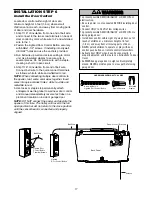
Page 17: ...to the 1 2 Fasten the Lighted Door Control Button securely with 6ABx1 1 2 screws If installing into drywall drill 5 32 holes and use the anchors provided 3 Run bell wire up wall and across ceiling to motor unit Use insulated staples to secure wire in several places Do not pierce wire with a staple creating a short or open circuit 4 Strip 7 16 of insulation from end of bell wire Connect bell wire t...

Page 18: ...f the rope through the hole in the release arm of the outer trolley Adjust rope length so the handle is 6 feet 1 83 m above the floor Ensure that the rope and handle clear the tops of all vehicles to avoid entanglement Secure with an overhand knot NOTE If it is necessary to cut the rope heat seal the cut end with a match or lighter to prevent unraveling To prevent possible SERIOUS INJURY or DEATH ...

Page 19: ...the black line wire to the screw on the brass terminal the white neutral wire to the screw on the silver terminal and the ground wire to the green ground screw The opener must be grounded Reinstall the cover To avoid installation difficulties do not run the opener at this time RIGHT WRONG To prevent possible SERIOUS INJURY or DEATH from electrocution or fire Be sure power is not connected to the o...

Page 20: ...oor Either can be installed on the left or right of the door as long as the sun never shines directly into the receiving eye lens The mounting brackets are designed to clip onto the track of sectional garage doors without additional hardware If it is necessary to mount the units on the wall the brackets must be securely fastened to a solid surface such as the wall framing Extension brackets see ac...

Page 21: ...ip hugging the back edge of the track as shown in Figure 1 If your door track will not support the bracket securely wall installation is recommended Wall installation Figure 2 3 Place the bracket against the wall with curved arms facing the door Be sure there is enough clearance for the sensor beam to be unobstructed If additional depth is needed an extension bracket See Accessories or wood blocks...

Page 22: ...t obstructed alignment is required Loosen the sending eye wing nut and readjust aiming directly at the receiving eye Lock in place Loosen the receiving eye wing nut and adjust sensor until it receives the sender s beam When the green indicator light glows steadily tighten the wing nut TROUBLESHOOTING THE SAFETY SENSORS 1 If the sending eye indicator light does not glow steadily after installation ...

Page 23: ...follows depending on your door s construction Metal or light weight doors using a vertical angle iron brace between the door panel support and the door bracket Drill 3 16 fastening holes Secure the door bracket using the two 1 4 14x5 8 self threading screws Figure 2A Alternately use two 5 16 bolts lock washers and nuts not provided Figure 2B Metal insulated or light weight factory reinforced doors...

Page 24: ...MINUM STEEL DOORS WITH GLASS PANEL ETC NOT PROVIDED ONE PIECE DOORS Please read and comply with the warnings and reinforcement instructions on the previous page They apply to one piece doors also Center the door bracket on the top of the door in line with the header bracket as shown Mark either the left and right or the top and bottom holes Metal Doors Drill 3 16 pilot holes and fasten the bracket...

Page 25: ...m are above holes in straight arm disconnect straight arm Cut about 6 15 cm from the solid end Reconnect to trolley with cut end down as shown Bring arm sections together Find two pairs of holes that line up and join with bolts lock washers and nuts Pull the emergency release handle toward the opener at a 45 angle so that the trolley release arm is horizontal Proceed to Adjustment Step 1 page 27 T...

Page 26: ...s 5 16 18 Lock Washers 5 16 Ring Fastener Straight Arm Bolts 5 16 18x7 8 Door Bracket Clevis Pin 5 16 x1 1 4 Curved Door Arm Press the Door Control push button The trolley will travel to the fully closed position Manually close the door and lift the door arm to the trolley The arm should touch the trolley just ahead of the door arm connector hole Refer to the fully closed trolley door arm position...

Page 27: ...in Adjustment Step 2 If the door does not close completely Increase down travel Turn the down limit adjustment screw counterclockwise One turn equals 2 5 cm of travel If door still won t close completely and the trolley bumps into the pulley bracket page 4 try lengthening the door arm page 25 and decreasing the down limit If the opener reverses in fully closed position Decrease down travel Turn th...

Page 28: ...lockwise Make small adjustments until the door completes a close cycle After each adjustment run the opener through a complete travel cycle Do not increase the force beyond the minimum amount required to close the door 2 Test the UP open force Grasp the door bottom when the door is about halfway through UP open travel The door should stop If the door is hard to hold or doesn t stop DECREASE UP ope...

Page 29: ...run the opener through 3 or 4 complete travel cycles to test adjustment If the unit continues to fail the Safety Reverse Test call for a trained door systems technician IMPORTANT SAFETY CHECK Test the Safety Reverse System after Each adjustment of door arm length limits or force controls Any repair to or adjustment of the garage door including springs and hardware Any repair to or buckling of the ...

Page 30: ...en power is restored after interruption when the opener is activated Light will also turn on when someone walks through the open garage door They will turn off automatically after 4 1 2 minutes Bulb size is 100 watts maximum IMPORTANT SAFETY INSTRUCTIONS To reduce the risk of severe injury or death WARNING WARNING WARNING 1 READ AND FOLLOW ALL WARNINGS AND INSTRUCTIONS 2 ALWAYS keep remote control...

Page 31: ... possible SERIOUS INJURY or DEATH from a falling garage door If possible use emergency release handle to disengage trolley ONLY when garage door is CLOSED Weak or broken springs or unbalanced door could result in an open door falling rapidly and or unexpectedly NEVER use emergency release handle unless garage doorway is clear of persons and obstructions NEVER use handle to pull door open or closed...

Page 32: ...for changing the code setting or replacing the battery THERE ARE NO OTHER USER SERVICEABLE PARTS Tested to Comply with FCC Standards FOR HOME OR OFFICE USE Operation is subject to the following two conditions 1 this device may not cause harmful interference and 2 this device must accept any interference received including interference that may cause undesired operation To prevent possible SERIOUS ...

Page 33: ...rse test after adjustments to force or travel limits The need for occasional adjustment for the force and limit settings is normal Weather conditions in particular can affect door travel Refer to Adjustment Step 1 Adjust the UP and DOWN Travel Limits Decrease down travel by turning down limit adjustment screw clockwise 5 My lights will not turn off when door is open The garage door opener is equip...

Page 34: ...wires together If motor unit activates replace door control If motor unit does not activate disconnect door control wires from motor unit Momentarily short across red and white terminals with jumper wire If motor unit activates replace door control wires Symptom Sending indicator light glows steadily receiving indicator light is dim or flashing Realign receiving eye sensor clean lens and secure br...

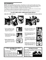
Page 35: ...OOR CONTROL PROGRAMMING 35 Your garage door opener has already been programmed at the factory to operate with your hand held remote control The door will open and close when you press the large push button Below are instructions for programming your opener to operate with additional Security remote controls LOCK LIGHT 1 Press and hold the button on the hand held remote that you wish to operate you...

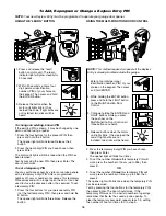
Page 36: ...r buttons for the present PIN then press and hold the button The opener light will blink twice Release the button 2 Press the new 4 digit PIN you have chosen then press Enter The motor unit lights will blink once when the PIN has been learned Test by pressing the new PIN then press Enter The door should move To set a temporary PIN You may authorize access by visitors or service people with a tempo...

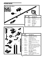
Page 37: ...remote control no circuit board 3 10A20 3V2032 Lithium battery 4 29B137 Remote control visor clip 5 41A2828 Emergency release rope and handle assembly 6 41B4494 1 2 Conductor bell wire white and white red 7 41A5047 1 Door bracket w clevis pin fastener 8 41A5047 2 Header bracket w clevis pin fastener 9 41A5034 Safety sensor kit receiving and sending eyes with 3 2 conductor bell wire 10 178B34 Strai...

Page 38: ... 108D67 Lens 8 30B532 Capacitor 1 2 HP 9 12A373 Capacitor bracket 10 41A3150 Terminal block w screws 11 41D3058 Universal replacement motor bracket assembly Complete with Motor worm bracket bearing assembly RPM sensor KEY PART NO NO DESCRIPTION 12 41A5525 31 Cover 13 41A2818 Limit switch drive retainer 14 41D3452 Limit switch assembly 15 41A2822 1 Interrupter cup assembly 16 41C4398A RPM sensor as...

Page 39: ...g the garage Sensor can be easily deactivated when desired 3 Button Mini Remote Control with SECURITY With key ring and fastening strip 956TV 940TV 10 Foot 3 06 m Rail Extension To allow a 10 foot 3 06 m door to open fully Multi Function Door Control Panel Provides a Lock feature which prevents operation of garage door opener from portable remotes and a Light feature for constant light 945CB CLDM1...

Page 40: ...e number Please include a brief description of the problem and a dated proof of purchase receipt with any product that is returned for warranty repair Products returned to Seller for warranty repair which upon receipt by Seller are confirmed to be defective and covered by this limited warranty will be repaired or replaced at Seller s sole option at no cost to you and returned pre paid Defective pa...

Page 41: ...te manual y las instrucciones de seguridad en él incluidas Al terminar la instalación deje el manual a mano cerca de la puerta del garaje La puerta NO SE CERRARÁ si el Protector System no está conectado y debidamente alineado Como medida de seguridad es conveniente efectuar inspecciones periódicas del mecanismo de apertura La etiqueta con el número de modelo se encuentra en el panel frontal del ab...

Page 42: ...do 8 11 Armado del riel e instalación del carro 8 Montaje del riel a la unidad motora e instalación de la polea guía 9 Instalación de la cadena cable 10 Ajuste de la cadena 11 Instalación 11 26 Instrucciones de seguridad para la instalación 11 Determinar la localización de soporte de cabecera 12 Instalación de la ménsula del cabezal 13 Colocación del riel en la ménsula del cabezal 14 Colocación de...

Page 43: ... trabas y seguros Quite toda cuerda conectada a la puerta del garaje Lleve a cabo la siguiente prueba para verificar que la puerta del garaje está balanceada y no tenga obstrucciones de movimiento 1 Levante la puerta hasta la mitad de su recorrido como se muestra Suelte la puerta Si está bien balanceada deberá mantenerse en esa posición con sólo el soporte de los resortes 2 Suba y baje la puerta o...

Page 44: ...Paso 10 de instalación Según el tipo de construcción del garaje podría ser necesario montar prolongaciones de ménsula o suplementos de madera para instalar los sensores Paso 10 de instalación Para la instalación alternativa del sensor de reversa de marcha de seguridad en el piso será necesario usar accesorios de fijación no suministrados con la unidad Perno de tope del carro Ménsula de cabecera Br...

Page 45: ...orios de fijación Véase la página 16 Pared frontal La separación entre el piso y la puerta no debe ser mayor de 1 4 6 mm Riel Motor Es normal cierto aflojamiento de la cadena con la puerta cerrada Sensor de reversa de seguridad Control de puerta montado en pared PUERTA DE UNA PIEZA SIN RIEL GUÍA Ménsula de cabecera Carro Cuerda y manija de desenganche de emergencia Ménsula de la puerta Brazo curvo...

Page 46: ... Sensores de reversa de seguridad 1 emisor y 1 receptor con cable de 2 conductores blanco y blanco negro conectado Su abre puertas viene empacado en una caja de cartón que contienen el motor y todas las piezas que se muestran en la siguiente ilustración Los accesorios incluidos van a depender del modelo que haya comprado Si falta alguna pieza revise con cuidado el material de empaque ya que podría...

Page 47: ... panel de pared 2 Pasador chaveta de 5 16 x1 1 Cuerda Arandela de presión de 5 16 7 Tirafondo de 5 16 9x1 5 8 2 Tornillo cabeza hexagonal de 5 16 18x7 8 4 Pasador chaveta de 5 16 x1 1 4 1 Tirafondo de 5 16 18x1 7 8 2 Tornillo de 6 32x1 2 Pasador chaveta de 5 16 x1 1 2 1 Tornillo autorroscante de 1 4 14x5 8 2 Manija Tornillo 6ABx1 1 4 2 Inventario de piezas Antes de la instalación organice todas la...

Page 48: ...rán orientados hacia abajo 1 Quite el brazo recto de acople a la puerta y la ménsula de suspensión que se encuentran empacados adentro del riel frontal y sepárelos para usarlos en los Pasos 5 y 12 de Instalación NOTA Para prevenir accidentes que podrían incluso causar LESIONES al desembalar el riel quite primero con cuidado el brazo recto de acople a la puerta empacado en su interior 2 Coloque los...

Page 49: ...inta de la polea guía El interior del centro debería estar engrasado Si así no fuera lubríquelo nuevamente Instale la polea en la abertura tal como se muestra en la ilustración Haga pasar el perno eje por el riel y la polea colocándolo desde arriba Ajuste la tuerca de presión de 3 8 hasta que la arandela de presión quede totalmente comprimida Haga girar la polea guía para asegurarse de que se muev...

Page 50: ...ado en el agujero del carro trole Verifique nuevamente que la cadena no se haya torcido ni torsionado Figura 4 7 Coloque la tuerca externa en el eje roscado del carro 8 Quite la pinza de sujeción usada como tope Cable Resorte del eslabón maestro Resorte del eslabón maestro Tapa del eslabón maestro Tapa del eslabón maestro Eje roscado del carro Eslabón del cable Ranura del pasador del cable Barra d...

Page 51: ...NSTALACIÓN Y LAS ADVERTENCIAS RELACIONADAS 2 Instale el abre puertas de garaje solamente en puertas de garaje que estén bien equilibradas y lubricadas Si la puerta no está debidamente equilibrada es posible que no retroceda cuando así se requiera y podría ocasionar una LESIÓN ACCIDENTAL GRAVE O INCLUSO LA MUERTE 3 Todas las reparaciones de los cables resortes y otras partes las DEBE llevar a cabo ...

Page 52: ...total supera la altura disponible de el garaje use la altura máxima posible o consulte la página 13 para obtener información sobre la instalación en el cielo raso Para evitar riesgos de LESIONARSE SERIAMENTE o de tener un accidente FATAL La ménsula de cabecera DEBE estar RÍGIDAMENTE fijada a un soporte estructural en la pared o en el techo en caso contrario el sistema de reversa podría no funciona...

Page 53: ...los agujeros verticales de la ménsula no utilice los agujeros destinados a montaje en cielo raso Haga los agujeros guía de 3 16 y fije la ménsula firmemente a un soporte estructural con los pernos incluidos Tirafondos de 5 16 x9x1 5 8 ACCESORIOS DE FIJACIÓN EN TAMAÑO REAL INSTALACIÓN DE LA MÉNSULA DEL CABEZAL EN EL CIELO RASO Prolongue la línea vertical de centro hasta el cielo raso tal como se mu...

Page 54: ...stuviera interfiriendo va a necesitar ayuda Otra persona tendrá que sostener el abre puertas firmemente sobre un soporte provisorio hasta que el riel pase el resorte Coloque la ménsula del riel contra la ménsula del cabezal Proceda a alinear los agujeros de las ménsulas y únalas con una chaveta de 5 16 x1 1 2 tal se muestra Introduzca un anillo de seguro para terminar la unión Caja del producto o ...

Page 55: ... para determinar la distancia ideal entre la puerta y el riel Quite el material de empaque Levante el abre puertas y colóquelo sobre una escalera Si la escalera no es lo suficientemente alta va a necesitar ayuda Abra la puerta totalmente y apoye acostado un tirante de madera de 2 x4 sobre la parte superior de la puerta bajo el riel Si la parte o el panel superior de la puerta toca el carro cuando ...

Page 56: ...e la puerta 7 Quite el tirante de madera de 2 x4 Opere la puerta manualmente Si la puerta toca el riel suba la ménsula del cabezal NOTA NO conecte todavía la alimentación eléctrica al abre puertas Para evitar la posibilidad de una LESIÓN GRAVE si se cayera accidentalmente el abre puertas fíjelo FIRMEMENTE a soportes estructurales del garaje Se DEBEN usar sujetadores para concreto si alguno de los ...

Page 57: ...respondientes al color del cable en la parte trasera de la unidad de control blanco a 2 y blanco y rojo a 1 2 Coloque el botón iluminado del control con tornillos 6ABx1 1 2 Si se instala el control en un panel hueco de pared hacer agujeros de 5 32 y fijarlo con los tarugos incluidos 3 Hacer el tendido del cable de timbre por la pared y el techo hasta el motor Fije el cable usando grampas con aisla...

Page 58: ...de la cuerda para que la manija quede a 6 pies 1 83 m sobre el nivel del piso Verifique que la cuerda y la manija queden a una altura superior a la de cualquier vehículo que entra al garaje Haga un nudo igual en ese extremo NOTA Si fuera necesario cortar la cuerda queme el extremo cortado con un fósforo o encendedor para evitar que el cordón se deshilache Para evitar la posibilidad de un accidente...

Page 59: ... al tornillo del terminal de bronce el cable blanco neutro al tornillo del terminal plateado y el cable de tierra al tornillo verde El abre puertas debe tener conexión a tierra Vuelva a colocar la tapa Para evitar problemas con la instalación no opere el abre puertas de garaje por ahora CORRECTO INCORRECTO Para evitar riesgos de accidentes GRAVES o FATALES por electrocución accidental o incendio A...

Page 60: ...or y el receptor siempre y cuando el receptor nunca reciba luz solar en forma directa Las ménsulas de montaje están disñadas para engancharse directamente a la guía de puertas seccionales de garajes sin necesidad de usar otros accesorios de fijación Si fuera necesario montar el dispositivo en la pared las ménsulas de montaje se deben fijar firmemente a una superficie sólida tal como el encofrado o...

Page 61: ...1 Si las ménsulas no quedan firmemente montadas en el perfil de la guía de la puerta es mejor instalarlas sobre la pared Instalación en pared Figuras 2 y 3 Coloque la ménsula contra la pared con los brazos curvos hacia el lado de la puerta Verifique que quede espacio suficiente para montar el sensor sin obstrucciones Si fuera necesario instalar las ménsulas con más separación de la pared se pueden...

Page 62: ...el mismo orientándolo directamente al receptor Vuelva a fijarlo en la nueva posición Afloje la tuerca mariposa del receptor y ajuste su posición hasta que reciba bien el haz de luz Cuando la luz verde quede encendida establemente ajuste nuevamente la tuerca mariposa DIAGNÓSTICO DE PROBLEMAS CON LOS SENSORES DE SEGURIDAD 1 Si la luz indicadora del emisor no quedara encendida permanentemente Verifiq...

Page 63: ...a con las siguientes instrucciones de instalación según el tipo de puerta Puertas metálicas o livianas con refuerzo vertical de hierro en ángulo entre la nervadura de soporte del panel de la puerta y la ménsula de la puerta Haga los agujeros de 3 16 para fijar la ménsula Fije la ménsula de la puerta con dos tornillos autorroscantes de 1 4 14x5 8 Figura 2A Como alternativa puede usar dos pernos de ...

Page 64: ...OS Ménsula de cabecera PUERTAS DE UNA SOLA PIEZA Lea y respete todas las advertencias e instrucciones respecto a los refuerzos contenidas en la página anterior ya que son válidas también para puertas de una sola pieza Centre la ménsula en la parte superior de la puerta alineada con la ménsula del cabezal tal se muestra en la ilustración Marque ya sea los orificios derecho e izquierdo o superior e ...

Page 65: ...amente 6 15 cm del lado que no tiene agujeros Vuelva a conectarlo al carro con el extremo cortado hacia abajo tal como se muestra en la ilustración Una las dos secciones del brazo Busque dos pares de orificios alineados y únalos con pernos arandelas y tuercas Tire de la manija de emergencia hacia el abre puertas en un ángulo de 45 para que el brazo de desenganche del carro quede horizontal Continú...

Page 66: ...ro Ajuste del cierre de la puerta disminución del límite del recorrido hacia ABAJO Gire el tornillo de ajuste del límite inferior cuatro vueltas completas en sentido horario Tuercas de 5 16 18 Arandelas de presión de 5 16 Anillo de seguro Brazo recto Pernos de 5 16 18x7 8 Ménsula de la puerta Pasador chaveta de 5 16 x1 1 4 Brazo curvo de la puerta Oprima el botón del control de la puerta El carro ...

Page 67: ...do antihorario Una vuelta equivale a 2 5 cm de recorrido Si la puerta aún no cierra por completo y el carro golpea la ménsula de soporte de polea página 4 pruebe a alargar el brazo de la puerta página 25 y disminuya el límite del recorrido hacia abajo Si el abre puertas invierte la dirección de movimienot en posición cerrada Disminuya el recorrido de cierre Gire el tornillo de ajuste de cierre DOW...

Page 68: ...e la puerta complete normalmente el movimiento de cierre Después de efectuar el ajuste haga funcionar el abre puertas un ciclo completo No aumente la fuerza más del mínimo necesario para cerrar la puerta 2 Prueba de fuerza de apertura hacia ARRIBA Tome la puerta por su parte inferior cuando está aproximadamente en la mitad de su recorrido de apertura La puerta debe detenerse Si no se detiene o es ...

Page 69: ...tas 3 o 4 ciclos completos para probar el ajuste de los movimientos Si el sistema de reversa de seguridad continuara fallando llame a un técnico espciaIista para efectuar la reparación VERIFICACIÓN IMPORTANTE DE SEGURIDAD Pruebe el sistema de reversa de seguridad después de Cada ajuste del largo del brazo de puerta de los límites de recorrido o de la fuerza de accionamiento Reparar o mantener la p...

Page 70: ...ta está abierta y alguien entre por ella al garaje Se apagará automáticamente a los 4 5 minutos La lámpara debe ser de 100 vatios máximo INSTRUCCIONES DE SEGURIDAD IMPORTANTES ADVERTENCIA ADVERTENCIA Para reducir el riesgo de lesiones graves o accidentes fatales 1 LEA Y RESPETE TODAS LAS ADVERTENCIAS E INSTRUCCIONES 2 SIEMPRE conserve los controles remotos lejos del alcance de los niños NUNCA perm...

Page 71: ...ATAL por la caída accidental de un puerta de garaje De ser posible use el desenganche de emergencia para soltar el carro SÓLO cuando la puerta del garaje esté CERRADA Si los resortes están debilitados o rotos o si la puerta está desbalanceada podría caerse rápida e inesperadamente NUNCA use la manija del desenganche de emergencia a menos que la entrada al garaje esté libre de obstrucciones y no ha...

Page 72: ...e dispositivo debe aceptar cualquier interferencia recibida incluyendo las que pudieran afectar su funcionamiento PROGRAMA DE MANTENIMIENTO Una vez al mes Operar la puerta manualmente Si está desequilibrada o se atasca llame a un técnico especializado para repararla Compruebe que la puerta se abra y se cierre totalmente Si fuera necesario reajuste los límites de recorrido y o de fuerza de accionam...

Page 73: ...espués de hacer ajustes de la fuerza o los límites de recorrido La necesidad de un reajuste ocasional de la fuerza y límites de recorrido es normal Las condiciones climatológicas en particular pueden afectar el recorrido de la puerta Consulte también Ajustes Paso 1 Ajuste de límites de recorrido de APERTURA y CIERRE Disminuya el recorrido de cierre hacia abajo girando el tornillos de ajuste en sen...

Page 74: ...ol Si el motor no arranca desconecte del panel del motor los cables que vienen del control Haga un puente momentáneo entre los terminales rojo y blanco Si el motor arranca cambie los cables entre el control y el motor Síntoma La luz indicadora del emisor está encendida normalmente pero la luz del receptor se enciende débilmente o intermitentemente Alinear el receptor limpiarlo y reajustar la ménsu...

Page 75: ...il USO DEL BOTÓN APRENDER LEARN USO DEL CONTROL MULTIFUNCIONAL DE LA PUERTA PROGRAMACIÓN 35 Su abre puertas de garaje ya viene programado de fábrica para operar con su control remoto La puerta se abrirá y se cerrará cuando oprima el botón grande A continuación se dan las instrucciones de programación del abre puertas para que funcione con otros controles remotos Security LOCK LIGHT 1 Oprima y mant...

Page 76: ... luego oprima y mantenga oprimido el botón La luz se encenderá dos veces Suelte el botón 2 Oprima el nuevo PIN de cuatro dígitos y luego oprima Enter Las luces del motor parpadearán una vez cuando el PIN se haya aprendido Pruebe oprimiendo el nuevo PIN luego oprima Enter La puerta debe moverse Programación de un PIN provisorio Usted puede autorizar el acceso a sus visitas o a personal de servicio ...

Page 77: ... tarjeta electrónica 3 10A20 Pila de litio de 3V2032 4 29B137 Broche de visera para control remoto 5 41A2828 Manija y cuerda de apertura de emergencia 6 41B4494 1 Cable de 2 conductores blanco y blanco rojo 7 41A5047 1 Ménsula de puerta con chaveta y perno 8 41A5047 2 Ménsula de cabezal con chaveta y perno 9 41A5034 Juego de sensores de seguridad receptor y emisor con 3 pies de cable de 2 conducto...

Page 78: ...e lámpara 7 108D67 Tulipa 8 30B532 Capacitor 1 2 HP 9 12A373 Retén del capacitor 10 41A3150 Bloque terminal con tornillos 11 41D3058 Motor de repuesto y soporte universal Completo incluyendo Motor sinfín soporte cojinete sensor de RPM REFER PARTE N N DESCRIPCIÓN 12 41A5525 31 Tapa 13 41A2818 Actuador y retén de límite de carrera 14 41D3452 Límite de carrera 15 41A2822 1 Tapa externa del interrupto...

Page 79: ...uien entre al garaje El sensor se puede desactivar fácilmente cuando así lo desee Minicontrol remoto de 3 botones SECURITY Con anillo llavero y banda sujetadora 956TV 940TV Prolongación de riel de 10 pies 3 06 m Para permitir la apertura completa de una puerta de 10 pies 3 06 m Panel multifuncional de control de puerta Tiene una función de bloqueo con la que se puede restringir la operación de la ...

Page 80: ...uidos de fábrica ESTA GARANTÍA LIMITADA SE OFRECE EN REEMPLAZO DE CUALQUIER OTRA GARANTÍA SEA EXPRESA O IMPLÍCITA Y AUN EN LUGAR DE TODA GARANTÍA IMPLÍCITA DE APTITUD DE COMERCIALIZACIÓN O APTITUD PARA CUMPLIR CON PROPÓSITOS PARTICULARES DE CUALQUIER ÍNDOLE TAMBIÉN EXIME AL VENDEDOR DE CUALQUIER OTRA OBLIGACIÓN O RESPONSABILIDAD AJENA A LOS TÉRMINOS EN ELLA ESTABLECIDOS ESTA GARANTÍA LIMITADA NO C...

Reviews: