background image

............ www.truemfg.com ............

True Food Service Equipment, Inc.

7

7

INSTALLATION / OPERATION INSTRUCTIONS

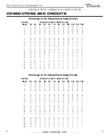
CONDUCTORS AND CIRCUITS

Wire Guage for 2% Voltage Drop in Supply Circuits.

  115 Volt      

Distance In Feet To Center of Load

  Amps  20  30  40  50  60  70  80  90  100  120  140  160


14 

14 

14 

14 

14 

14 

14 

14 

14 

14 

14 

14


14 

14 

14 

14 

14 

14 

14 

14 

14 

14 

14 

12


14 

14 

14 

14 

14 

14 

14 

14 

14 

12 

12 

12


14 

14 

14 

14 

14 

14 

14 

12 

12 

12 

10 

10


14 

14 

14 

14 

14 

14 

12 

12 

12 

10 

10 

10


14 

14 

14 

14 

14 

12 

12 

12 

10 

10 

10 

8


14 

14 

14 

14 

12 

12 

12 

10 

10 

10 

8


14 

14 

14 

12 

12 

12 

10 

10 

10 

8


10 

14 

14 

14 

12 

12 

10 

10 

10 

10 

8


12 

14 

14 

12 

12 

10 

10 

10 

6


14 

14 

14 

12 

10 

10 

10 

6


16 

14 

12 

12 

10 

10 

6


18 

14 

12 

10 

10 

5


20 

14 

12 

10 

10 

5


25 

12 

10 

10 

4


30 

12 

10 

3


35 

10 

10 

2


40 

10 

2


45 

10 

1


50 

10 

1

Wire Guage for 2% Voltage Drop in Supply Circuits.

  230 Volt      

Distance In Feet To Center of Load

  Amps  20  30  40  50  60  70  80  90  100  120  140  160


14 

14 

14 

14 

14 

14 

14 

14 

14 

14 

14 

14


14 

14 

14 

14 

14 

14 

14 

14 

14 

14 

14 

12


14 

14 

14 

14 

14 

14 

14 

14 

14 

14 

12 

12


14 

14 

14 

14 

14 

14 

14 

14 

14 

12 

12 

12


14 

14 

14 

14 

14 

14 

14 

14 

12 

12 

12 

10


10 

14 

14 

14 

14 

14 

14 

14 

12 

12 

12 

10 

10


12 

14 

14 

14 

14 

14 

14 

12 

12 

12 

10 

10 

10


14 

14 

14 

14 

14 

14 

12 

12 

12 

10 

10 

10 

8


16 

14 

14 

14 

14 

12 

12 

12 

10 

10 

10 

8


18 

14 

14 

14 

12 

12 

12 

10 

10 

10 

8


20 

14 

14 

14 

12 

10 

10 

10 

10 

10 

8


25 

14 

14 

12 

12 

10 

10 

10 

10 

6


30 

14 

12 

12 

10 

10 

10 

6


35 

14 

12 

10 

10 

10 

5


40 

14 

12 

10 

10 

5


50 

12 

10 

10 

4


60 

12 

10 

3


70 

10 

10 

2


80 

10 

2


90 

10 

1


100 

10 

1

Summary of Contents for TCGD-50

Page 1: ...ment 800 424 TRUE Parts Department FAX 636 272 9471 TABLE OF CONTENTS Safety Information Safety Precautions 1 Proper Disposal 2 Connecting Electricity 3 Adapter Plugs 3 Installation Operation Instruct...

Page 2: ......

Page 3: ...and between the doors and cabinet are necessarily small be careful closing doors when children are in the area NOTE We strongly recommend that any servicing be performed by a qualified individual WARN...

Page 4: ...on cord applies to cabinets ordered with optional 12 power cord Child entrapment and suffocation are not problems of the past Junked or abandoned display cases are still dan gerous even if they will s...

Page 5: ...e plugged into it s own individual electrical circuit which has a voltage rating that matches the rating plate This provides the best performance and also prevents overloading building wiring circuits...

Page 6: ...E is not responsible for damage incurred during shipment OWNERSHIP Tin Snips Band Cutters Claw Hammer Hex Head Driver Adjustable Wrench 3 4 19 mm Open End Wrench Phillips Head Screwdriver Level REqUIR...

Page 7: ...net LOCATING A Set unit in its final location B Proper leveling of your TRUE unit is critical to operating success for non mobile models Effective door operation will be effected by leveling WARNING D...

Page 8: ...wiring diagram is positioned on the ballast box inside lower rear of the cabinet ELECTRICAL INSTRUCTIONS A Verify that the cabinet lights are working Bakery cases are shipped with light switches in th...

Page 9: ...8 6 6 6 6 5 4 4 3 35 10 10 8 6 6 6 5 5 4 4 3 2 40 10 8 8 6 6 5 5 4 4 3 2 2 45 10 8 6 6 6 5 4 4 3 3 2 1 50 10 8 6 6 5 4 4 3 3 2 1 1 Wire Guage for 2 Voltage Drop in Supply Circuits 230 Volt Distance In...

Page 10: ...t notch of shelf support image 3 E Install rear brackets by sliding end hooks over rear notch of shelf support image 4 F Locate shelves install top shelf first With the front lip tray stop up and towa...

Page 11: ...cked out by hand image 1 C Take two threaded castors and thread them into the existing leg leveler holes image 2 Shims can be used between castor and cabinet frame rail for leveling image 3 Use the to...

Page 12: ...they each can be used for left or right of the cabinet Slide panel up into black plastic tracks on the top side panel of each end of cabinet images 1 3 NOTE After installing the bottom end pieces the...

Page 13: ...res TRUE rec ommends either of the following methods A Using a vinyl cove base trim as produced by Armstrong Johnson or Kentile available at floor cover ing suppliers or Using mastics available at har...

Page 14: ...spring loaded lampholder E Reinstall light assembly and shelf Plug cord into side wall receptacle INTERIOR TOP BULB REPLACEMENT WARNING When replacing a light bulb make sure power to the unit is eithe...

Page 15: ...s in the system 500 microns or lower must be obtained WARRANTY CLAIMS All claims for labor or parts must be made directly through TRUE All claims should include model number of the unit the serial num...

Reviews: