
............ www.truemfg.com ............
True Food Service Equipment, Inc.
5
5
INSTALLATION / OPERATION INSTRUCTIONS
TOOLS REQUIRED:
• Phillips screw driver
•
3
/
8
” (9.5 mm) socket or
3
/
8
” (9.5 mm) wrench
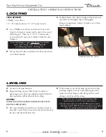
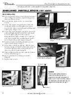
A.
Use a Phillips screw diver and remove four screws
from the L-bracket connected the unit to the wood
skid (image 1). Then use a 3/8” (9.5 mm) socket
or wrench and remove the L-bracket from the unit
(image 2).
To avoid damage to glass DO NOT lay cabinet
on its side or back when removing skid,
installing leg levelers, cleaning, etc.
B.
Lift up from the base and walk unit off the skid and
set in final location.
C.
Unblock doors, (free plastic wedges, blue foam and
tape. Remove fiberglass tape securing glass.
Remove components: (shelves, brackets, etc.) from
inside cabinet.
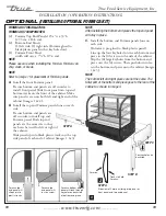
LOCATING
A.
Set unit in its final location.
B.
Proper leveling of your TRUE unit is critical to
operating success (for non-mobile models). Effective
door operation will be effected by leveling.
WARNING
Display case must be leveled accurately to ensure front
glass door seals properly.
C.
The unit should be leveled front to back and side to
side with a level. Place the level in the interior floor of
the unit and check all four sides.
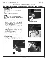
D.
If the cabinet is not level adjust leg levelers by first
relieving weight to leveler and adjusting by either
hand or wrench. Repeat with all leg levelers until
cabinet is level in all directions.
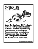
Dry bakery cases require hard wiring unless
ordered with 12" (30.5 cm) cord option.
Cabinet warranties are void if OEM power cord is
tampered with. TRUE will not warranty any units
that are connected to an extension cord.
LEvELING
Removing bracket from skid.
1
2
Removing bracket from cabinet.
Summary of Contents for TCGD-50
Page 2: ......