background image

Page 12

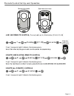
Remote Control Set-Up and Operation

ADD ONE REMOTE CONTROL 

(You can add up to 20 remotes, ID from 01-20)

DELETE ONE EXISTING REMOTE CONTROL

DELETE ALL REMOTE CONTROLS

Hear 1 beep and Light Indicator illuminates green.

Note: This is the only step you need to use the remote for programming.

Hear 1 beep and Light Indicator illuminates green.

Note: You must have more than 1 remote synced to this lock to DELETE ONE OR ALL REMOTES

Hear 1 beep and Light Indicator illuminates green.

7                 Existing      (01-20)          re-enter

8                 Existing      (01-20)           re-enter

9                 re-enter

PC

PC

PC

PC

ID

ID

ID

ID

Press any 

button on 

the remote

Summary of Contents for 08102017

Page 1: ...USER MANUAL ELECTRONIC DEADBOLT WITH REMOTE 08102017...

Page 2: ...Low Battery Warning Consumer Friendly Message Guide Page 14 Installation Trouble Shooting Page 15 Consumer Assistance Page 16 Template Page 17 18 Programming Record Page 19 20 Limited Warranty Page 2...

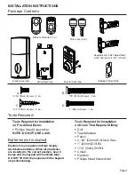
Page 3: ...Hammer Phillips Head Screwdriver Deadbolt Strike Plate Deadbolt Latch Set Adjustable 2 3 8 60mm to 2 3 4 70mm Interior Assembly Mounting Plate Exterior Assembly Entry keys 2 ea Wireless Remote 1 ea 5...

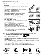
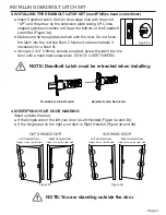
Page 4: ...sert Deadbolt Latch Assembly in hole keeping it parallel to face of door Mark outline and remove latch Figure 3c d Chisel 1 8 3mm deep or until latch face is flush with door edge Figure 3d 4 MARK AND...

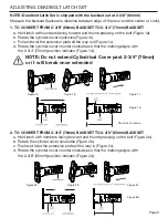
Page 5: ...inder cover counter clockwise so that the marking aligns with the 2 3 4 70mm position indicator Figure 1d 2 TO CONVERT FROM 2 3 4 70mm BACKSET TO 2 3 8 60mm BACKSET a Hold latch with numbers facing fo...

Page 6: ...into the door with a hand held screwdriver DO NOT OVER TIGHTEN 4 IDENTIFYING YOUR DOOR HANDING Stand outside the door a If the hinges are on the left your door is Left Handed Figure 4a and 4b b If the...

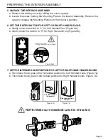
Page 7: ...izontal position for Left Handed Doors Figure 7a b The Interior Knob goes in the Vertical position for Right Handed Doors Figure 7b Entry Switch Left or Right Figure 6a b NOTE Make sure deadbolt Latch...

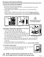
Page 8: ...Mounting Plate upper hole as a guide Figure 10a b Insert one 3 4 19mm screw C and tighten 8 INSTALLING THE EXTERIOR ASSEMBLY Work with the Door Open for easy access a Unpack the Exterior Assembly Use...

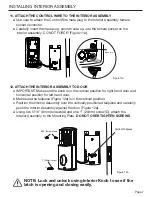
Page 9: ...cal position for right hand door and horizontal position for left hand door b Make sure the tailpiece Figure 12a is in the vertical position c Position the Interior Assembly over the vertically positi...

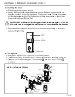
Page 10: ...ck a Always test with the Door Open and in unlocked position b Test the Lock using the Interior Knob The bolt should move smoothly in and out c Test the Lock using the Keypad To lock press and then pr...

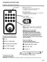
Page 11: ...the keypad until the keypad stops illuminating 5 Seconds Complete all the programming steps in the programming mode within 5 seconds Lock Used to lock door Lock button Unlock Used to unlock door Progr...

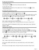
Page 12: ...er ID ID which is any number between 01 50 to identify an individual User Code UC User ID ID 1 9 should be entered as 01 09 so they are 2 digits Hear 1 beep and Light Indicator illuminates green Recor...

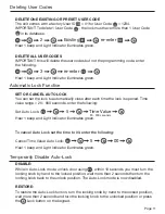
Page 13: ...es green To cancel Auto Lock set the time to 00 enter the following Cancel Time Value Auto Lock Hear 1 beep and Light Indicator illuminates green Hear 1 beep and Light Indicator illuminates green 2 Ex...

Page 14: ...cator illuminates green Note This is the only step you need to use the remote for programming Hear 1 beep and Light Indicator illuminates green Note You must have more than 1 remote synced to this loc...

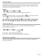
Page 15: ...ion Mode Hear 1 beep and Light Indicator illuminates green then lock door 10 1 PC NOTE If you only press the for more than 3 seconds but do not input PC the system will remain in Vacation Mode You can...

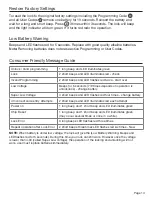
Page 16: ...4 Incorrect code entry attempts 2 short beeps and LED illuminates red each attempt Power on 1 long beep and 1 short beep and LED illuminates green Chip Reset 1 long beep and 1 short beep and LED illu...

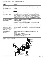
Page 17: ...ronically Check that all batteries are fresh high quality Alkaline Batteries Check for proper polarity of all batteries Check that the Control Wire is attached to the Interior Assembly Lock gives erro...

Page 18: ...Sandhill Avenue Carson CA 90746 USA TELEPHONE US Canada 800 860 1677 Ext 1801 Toll Free CALL CENTER HOURS US Canada 7am 5pm Pacific Mon Fri Subject to change CALL BACK HOURS Other Countries 7am 5pm Pa...

Page 19: ...CE TEMPLATE ON HIGH EDGE OF DOOR BEVEL THEN DRILL 1 25mm HOLE IN CENTER OF DOOR EDGE 2 IN DEPTH FOLD HERE ON DOOR EDGE 2 8 BACKSET 3 MARK FOR 1 45mm DOOR 3 4 DRILL 2 1 8 54mm HOLE MARK CENTER OF HOLE...

Page 20: ...Page 18 Back of Template...

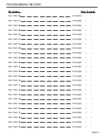
Page 21: ...igits User Code 08 4 8 digits User Code 09 4 8 digits User Code 10 4 8 digits User Code 11 4 8 digits User Code 12 4 8 digits User Code 13 4 8 digits User Code 14 4 8 digits User Code 15 4 8 digits Us...

Page 22: ...de 33 4 8 digits User Code 34 4 8 digits User Code 35 4 8 digits User Code 36 4 8 digits User Code 37 4 8 digits User Code 38 4 8 digits User Code 39 4 8 digits User Code 40 4 8 digits User Code 41 4...

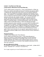
Page 23: ...shall Tru Bolt be liable for any special incidental or consequential damages If this product s is considered a consumer product please be advised that some local and state laws do not allow limitatio...

Reviews: