Page 15
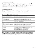
Unlock / Valid programming
1 long beep and LED illuminates green
Lock
2 short beeps and LED illuminates red - check
Invalid Programming
2 short beeps and LED flashes red twice - start over
Low Voltage
Beeps for 5 seconds (7/9 times depends on operation is
unlock/lock) - change battery
Super Low Voltage
4 short beeps and LED flashes red four times - change battery
4 Incorrect code entry attempts
2 short beeps and LED illuminates red each attempt
Power on
1 long beep and 1 short beep and LED illuminates green
Chip Reset
1 long beep and 1 short beep and LED illuminates green
(may occur several times or once in a while)
Lock Error
3 long beeps LED flashes red three times
Repeat operation after Lock Error
2 short beeps three times LED flashes red six times - New
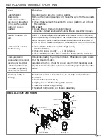
INSTALLATION TROUBLE SHOOTING
Issue
Solution
Latch Working
Backwards-
Lock unlocks when
lock button is pushed
or locks when unlock
button or code is
pushed.
Direction switch is set to incorrect setting.
Remove the Interior Assembly and move the switch to the opposite
direction.
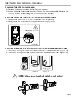
• Check that your switch is set in the correct position Left or Right
Handed door.
If Correct
• Rotate Interior Knob and reinstall Interior
Assembly. Retest again while holding Interior Assembly in place.
Interior Knob will not
turn.
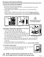
Knob or vertical tailpiece is installed in incorrect position. Remove
Interior Assembly and reposition the Interior Knob. With the Deadbolt
Latch retracted verify that the tailpiece is vertical or if extended to
2 3/8” to 2 3/4” check position the cross and that latch is not locked.
Lock will not function
electronically.
• Check that all batteries are fresh high quality
Alkaline Batteries.
• Check for proper polarity (+ -) of all batteries.
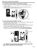
• Check that the Control Wire is attached to the Interior Assembly.
Lock gives error
signal when opening or
locking and Deadbolt
Latch will not extend
or retract completely
when door is closed.
Unlock door using Key or Interior Knob. While door is open, check
that the Deadbolt Latch
operates smoothly. Check for proper alignment of the strike plate,
adjust as needed to assure there is no binding against the Deadbolt
Latch.
Deadbolt Latch is
sticking.
Installation screws of the lock may be too tight and have to be
loosened.
• Remove Interior Assembly.
• Slightly loosen the Mounting Plate screws.
• Lock and unlock using the Key.
• Reattach Control Wire and Interior Assembly.
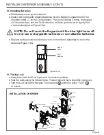
INSTALLATION OVERVIEW
Strike Plate
3/4” (19mm) screws(C)
Mounting Plate
Interior Assembly
Optional
3/4”(19mm) Screw(C)
7/8”(22mm) screws(B)
Latch
Exterior Assembly
Control Wire
Rubber Gasket
Key
Remote
Battery Cover
5/16”(8mm)
screws(A)
1”(25mm)
Screw(D)

