


BA 8010_3.0_EN (10/2016)
40 / 68
There are three methods to focus the laser beam:
A
:
Manual focusing
B
:
Focusing by software
C
:
Automatic focusing by means of light barriers (optional)
To
A
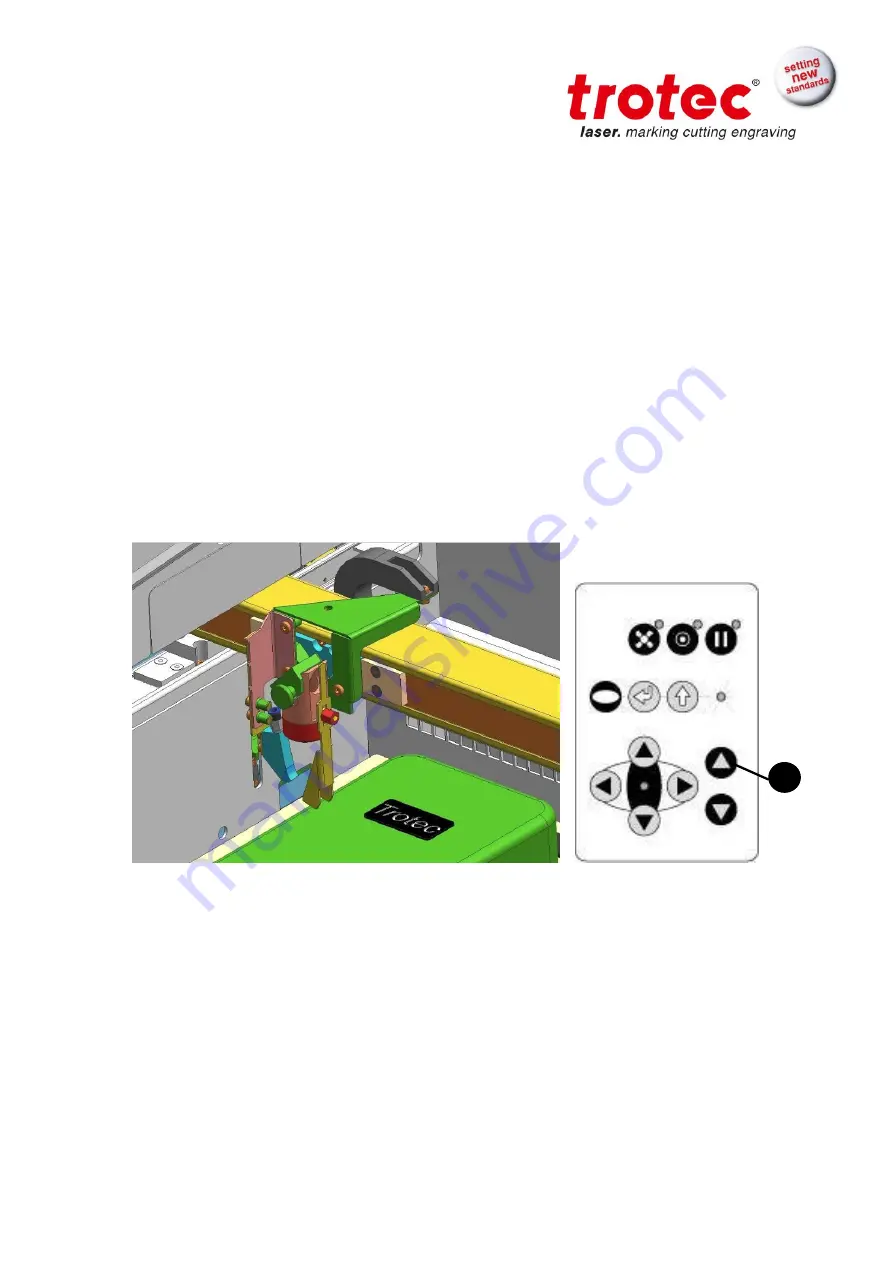
– Manual focusing:
A1.
Move the processing head over the material to be engraved by means
of the positioning keys X/Y
A2.
Hang the focus tool on the external ring of the working head so that the
focus tool can move unhindered. Move the working table upwards by
pressing the Z positioning key
(1)
. While doing this carefully observe the
focus tool.
Before the focus tool reaches the work piece, move the working table
upwards only very slowly and step by step by briefly tapping the
positioning key, until the tool tilts to the side. Now the lens is focused
onto the surface of the material.
1
Summary of Contents for Speedy 100
Page 1: ...BA 8010_3 0_EN 10 2016 1 68 OPERATION MANUAL 8010 Trotec Speedy 100 R ...
Page 17: ...BA 8010_3 0_EN 10 2016 17 68 ...
Page 28: ...BA 8010_3 0_EN 10 2016 28 68 10 Maintenance panel ...
Page 30: ...BA 8010_3 0_EN 10 2016 30 68 Used to align material and measure it ...
Page 39: ...BA 8010_3 0_EN 10 2016 39 68 ...
Page 43: ...BA 8010_3 0_EN 10 2016 43 68 ...
Page 57: ...BA 8010_3 0_EN 10 2016 57 68 7 Replace the mirror and fix it again with the two Allen screws ...
Page 67: ...BA 8010_3 0_EN 10 2016 67 68 ...


